Bearing device with sensor and rolling bearing with sensor
A technology of rolling bearings and sensors, which is applied in bearing assembly, measuring devices, bearing components, etc., can solve the problems of increasing assembly man-hours, restricting miniaturization, increasing the number of parts and cost, etc., to improve tensile strength, reduce assembly man-hours, reduce The effect of the number of parts
- Summary
- Abstract
- Description
- Claims
- Application Information
AI Technical Summary
Problems solved by technology
Method used
Image

Examples
no. 1 approach
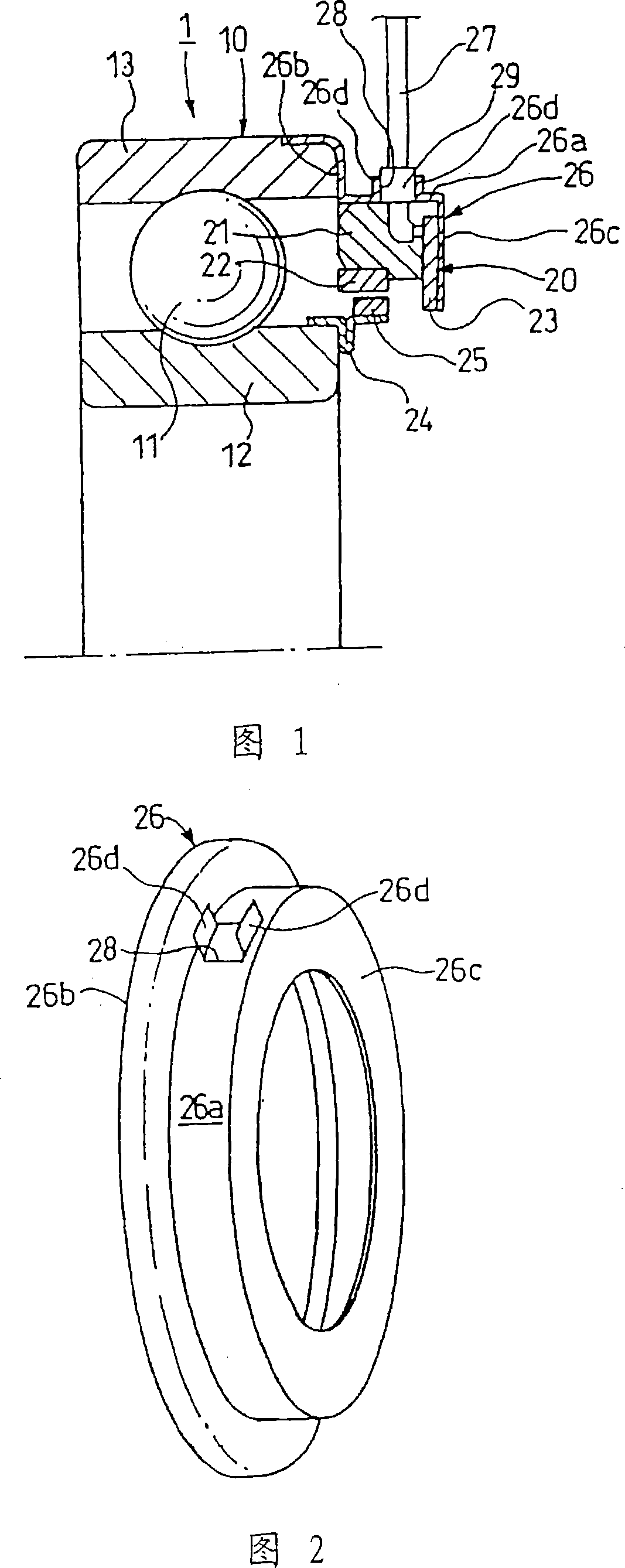
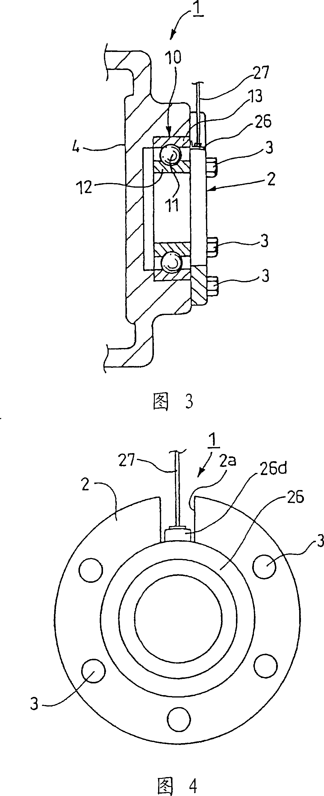
[0114] Fig. 1 is a sectional view of main parts showing a first embodiment of a sensor-equipped bearing device according to the present invention. Fig. 2 is a perspective view showing a sensor cover of the sensor-equipped bearing device of Fig. 1 . 3 is a cross-sectional view of main parts showing a state in which the sensor-equipped bearing device of FIG. 1 is fixed on the bearing housing; FIG. 4 is a right side view of FIG. 3; FIG. picture.
[0115] As shown in FIG. 1 , the sensor-equipped bearing device 1 has a rolling bearing 10 . The rolling bearing 10 has an inner ring 12 as a rotating side ring, an outer ring 13 as a fixed side ring, and a plurality of rolling elements 11 rotatably interposed between the inner ring 12 and the outer ring 13 . The plurality of rolling elements 11 are held at equal intervals in the circumferential direction by cages not shown.
[0116] In addition, the sensor-equipped bearing device 1 has a sensor 20 capable of detecting the state of th...
no. 2 approach
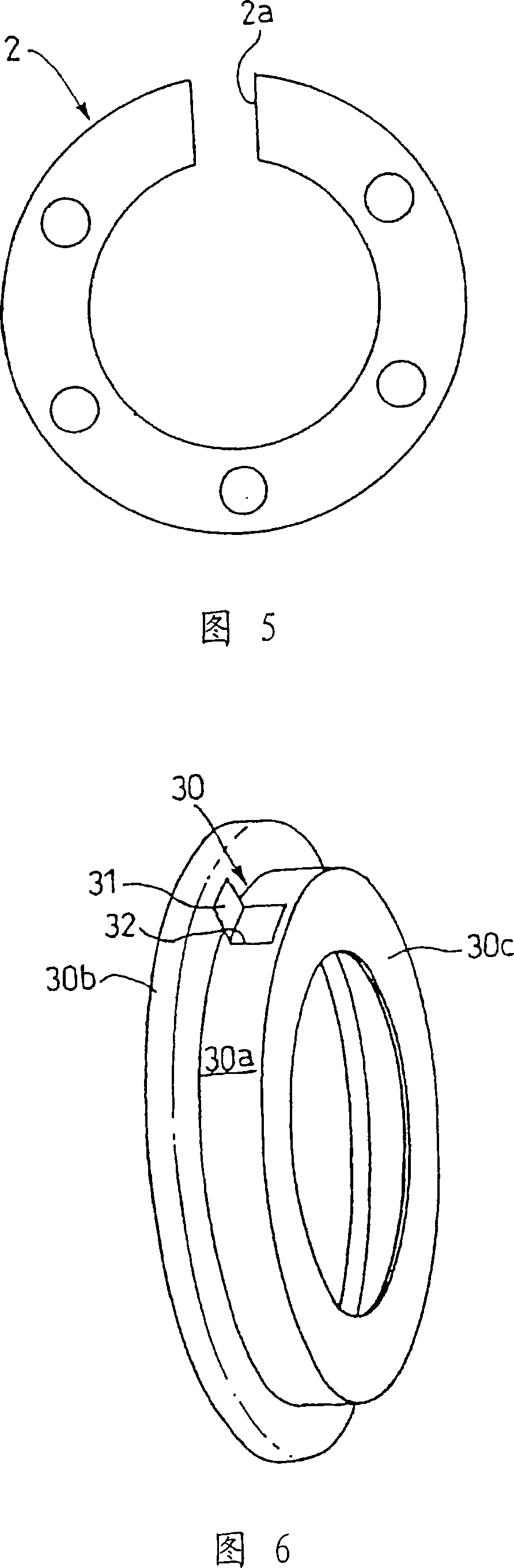
[0135] Fig. 6 is a perspective view illustrating a second embodiment of the sensor-equipped bearing device of the present invention. In addition, in the embodiment described below, the same code|symbol or equivalent code|symbol etc. is attached|subjected to the member etc. which have the structure and function equivalent to what already demonstrated, and description is simplified or omitted.
[0136] In the present embodiment, the protruding portion 31 of the sensor cover 30 is bent so as to protrude in the radial direction by forming a cutout portion of a part of the sensor cover 30 to form a single-leaf hinged door shape.
[0137] Other structures and functions are the same as those of the above-mentioned first embodiment.
no. 3 approach
[0139] 7 is a perspective view showing a sensor cover of a rolling bearing of a sensor-equipped bearing device according to a third embodiment of the present invention.
[0140] In the present embodiment, the protruding portion 41 of the sensor cover 40 is formed by bending a part of the sensor cover 40 to protrude in the radial direction toward the side (the side surface portion 40 c ) axially opposite to that of the second embodiment to form a single-leaf hinge. door shape.
[0141] Other structures and functions are the same as those of the above-mentioned first embodiment and second embodiment.
PUM
 Abstract
Description
Claims
Application Information
 - R&D
- Intellectual Property
- Life Sciences
- Materials
- Tech Scout
- Unparalleled Data Quality
- Higher Quality Content
- 60% Fewer Hallucinations
Browse by: Latest US Patents, China's latest patents, Technical Efficacy Thesaurus, Application Domain, Technology Topic, Popular Technical Reports.
© 2025 PatSnap. All rights reserved.Legal|Privacy policy|Modern Slavery Act Transparency Statement|Sitemap|About US| Contact US: help@patsnap.com