Granule material vibration cooling machine

A technology for granular materials and coolers, applied to direct contact heat exchangers, heat exchanger types, lighting and heating equipment, etc., can solve problems such as long-term storage, loss of manufacturers, hardening, etc., and facilitate inspection and maintenance , Improve the cooling effect and avoid the effect of material leakage

CN101187533AInactive Publication Date: 2008-05-28河南金谷干燥工程技术有限公司
0 Cites 15 Cited by

Patent Information

Authority / Receiving Office
CN · China
Patent Type
Applications(China)
Current Assignee / Owner
Publication Date
2008-05-28
Estimated Expiration
Not applicable · inactive patent

Smart Images

  • Figure 1
    Figure 1
  • Figure 2
    Figure 2
  • Figure 3
    Figure 3
Patent Text Reader

Abstract

A granular material vibrating cooler comprises a ventilating mechanism, wherein a material cooling chamber and a vibrating mechanism are fixedly mounted on the a base, a material inlet and an air outlet are arranged on the upper portion of the material cooling chamber, and a material outlet is arranged on the lower portion, air inlets are evenly arranged on two corresponding lateral wall of the material cooling chamber, the air inlet is connected with an air inlet pipe, the ventilating mechanism which is mounted in the material cooling chamber is provided with a plate-frame skeleton and a certain amount of air grooves. An opening of the air groove is arranged downwards, the air grooves which have at least two layers are alternately arrayed in parallel and penetrated through and fixed on the plate-frame skeleton, two ends of the air groove are positively faced to the air inlets and communicated with the air inlets. The plate-frame skeleton is connected with the ventilating mechanism by penetrating the two lateral wall of the material cooling chamber through a connecting piece. The granular material vibrating cooler adopts the mode that cold air blast is combined with vibration, which has a good cooling effect on high temperature material, in particular to composite fertilizer which is being cooled. The invention cools completely, which can not being hardened, and is benefit to popularization and application.
Need to check novelty before this filing date? Find Prior Art

Description

1. Technical field

[0001] The invention is a cooling device for granular materials, which is suitable for cooling after granulation in grain, chemical and other industries. 2. Background technology

[0002] For example, in the production process of compound fertilizer, it needs to be mixed, tempered and made into spherical shape, and then dried. Since the spherical compound fertilizer contains high water content, it needs to be dried in a high-temperature kiln at 60-80°C for a period of time to meet the requirement of a water content of less than 5%, and chemical reactions are carried out during the process. The compound fertilizer after heating and drying must be cooled. Otherwise, hardening will occur immediately, making subsequent dressing, spraying, and packaging processes impossible. The compound fertilizer with too high temperature cannot be stored for a long time, otherwise it will cause serious hardening, which will cause difficulties for farmers to use. The compo...

Examples

Embodiment 1

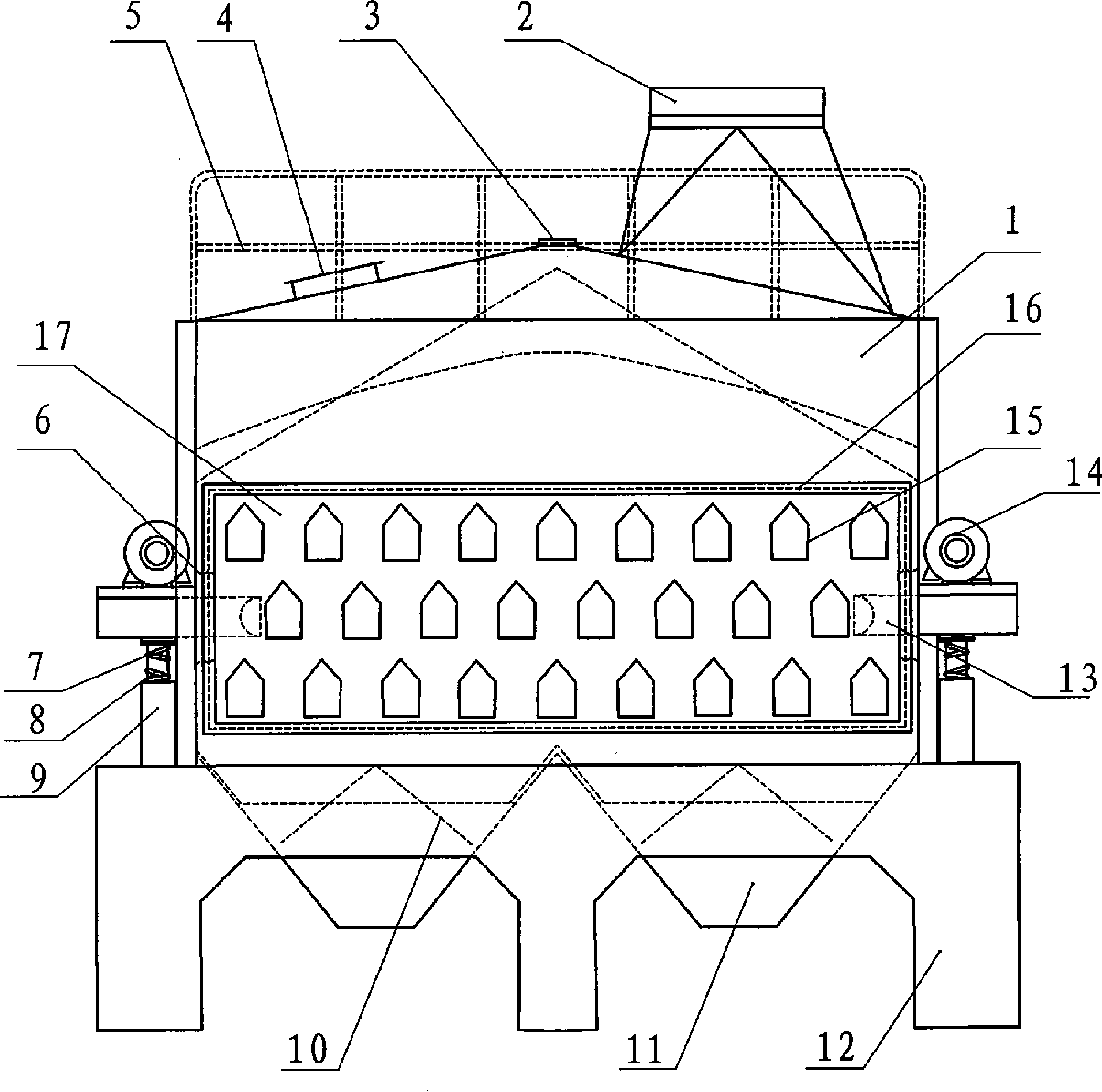
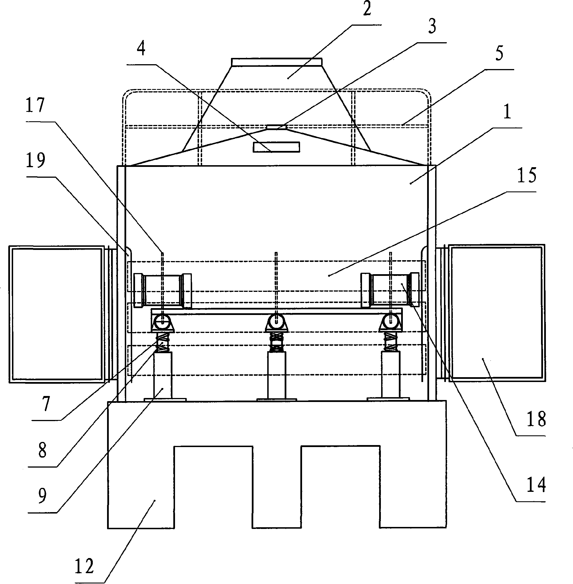
[0027] Embodiment one: see figure 1 , figure 2 , one A granular material vibrating cooler, including a ventilation mechanism, a material cooling chamber 1 and a vibrating mechanism are fixedly installed on a base 12, the upper part of the material cooling chamber 1 is provided with a material inlet 3 and an air outlet 2, and the lower part is provided with an outlet The feed port 11 is provided with an air inlet 16 on both corresponding side walls of the material cooling chamber 1, and the air inlet 16 is connected to the air inlet pipe 18; the ventilation mechanism is installed in the material cooling chamber 1 and includes a plate frame Skeleton 17, a certain number of air grooves 15; the air grooves 15 are opened downward, and the air grooves 15 are at least two layers, arranged in parallel and staggered, passing through and fixed on at least two of the above-mentioned plate frame skeletons 17; The two ends of the air groove 15 face the air inlet 16 and communicate with...

Embodiment 2

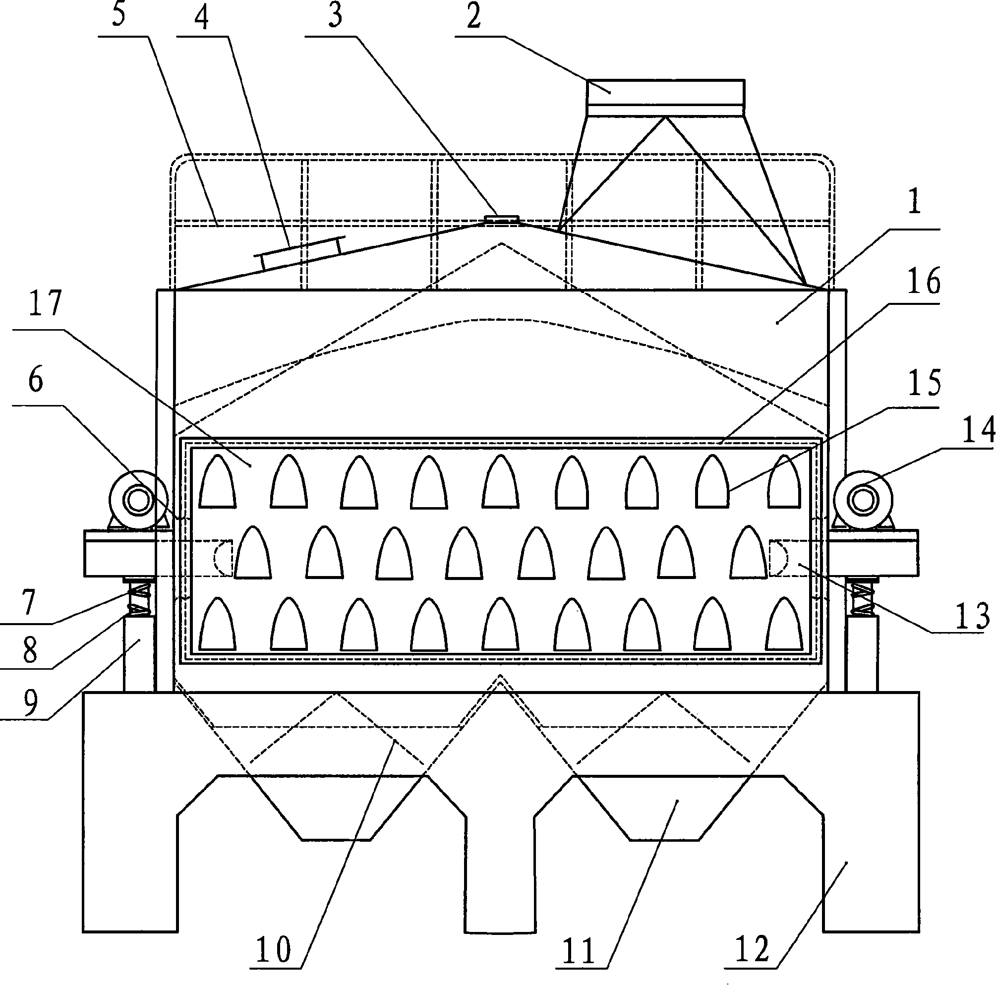
[0029] Embodiment two: see figure 2 , image 3 , Embodiment 2 is basically the same as Embodiment 1. The same symbols in the figure represent the same meanings, and the same parts will not be repeated. The difference is that the cross section of the air duct 15 described in Embodiment 2 is a hollow parabolic shape.

Embodiment 3

[0030] Embodiment three: see figure 2 , Figure 4 Embodiment 3 is basically the same as Embodiment 1. The same symbols in the figure represent the same meanings, and the similarities will not be repeated. The difference is that the cross-section of the ventilation groove 15 described in Embodiment 3 is a hollow elliptical arc.