Substrate carrying in/out apparatus, substrate carrying method and device thereof

A substrate handling and substrate technology, which is applied in the field of substrate devices, can solve the problems that are not suitable for the manufacture of products with short lead times, the production time cannot be achieved, and the turnover rate (recovery rate becomes poor, etc.)

Inactive Publication Date: 2008-05-28
SHINKO ELECTRIC CO LTD
View PDF4 Cites 9 Cited by
  • Summary
  • Abstract
  • Description
  • Claims
  • Application Information

AI Technical Summary

Problems solved by technology

Therefore, it is not suitable for the manufacture of products with short lead times
In addition, due to the long production time T12 of the product, it cannot be counted as a product, and the number of unfinished products (work-in-progress inventory) remaining in the manufacturing line like inventory is large. Therefore, from the perspective of management, the turnover rate of invested capital ( Recovery rate) becomes worse
Also, in recent years, the above problems have become more pronounced as substrates have become larger and thus more expensive.

Method used


Image

  • Substrate carrying in/out apparatus, substrate carrying method and device thereof
  • Substrate carrying in/out apparatus, substrate carrying method and device thereof
  • Substrate carrying in/out apparatus, substrate carrying method and device thereof

Examples


no. 1 example

[0132] First, the board loading / unloading device of the present invention will be described based on the first to third embodiments.

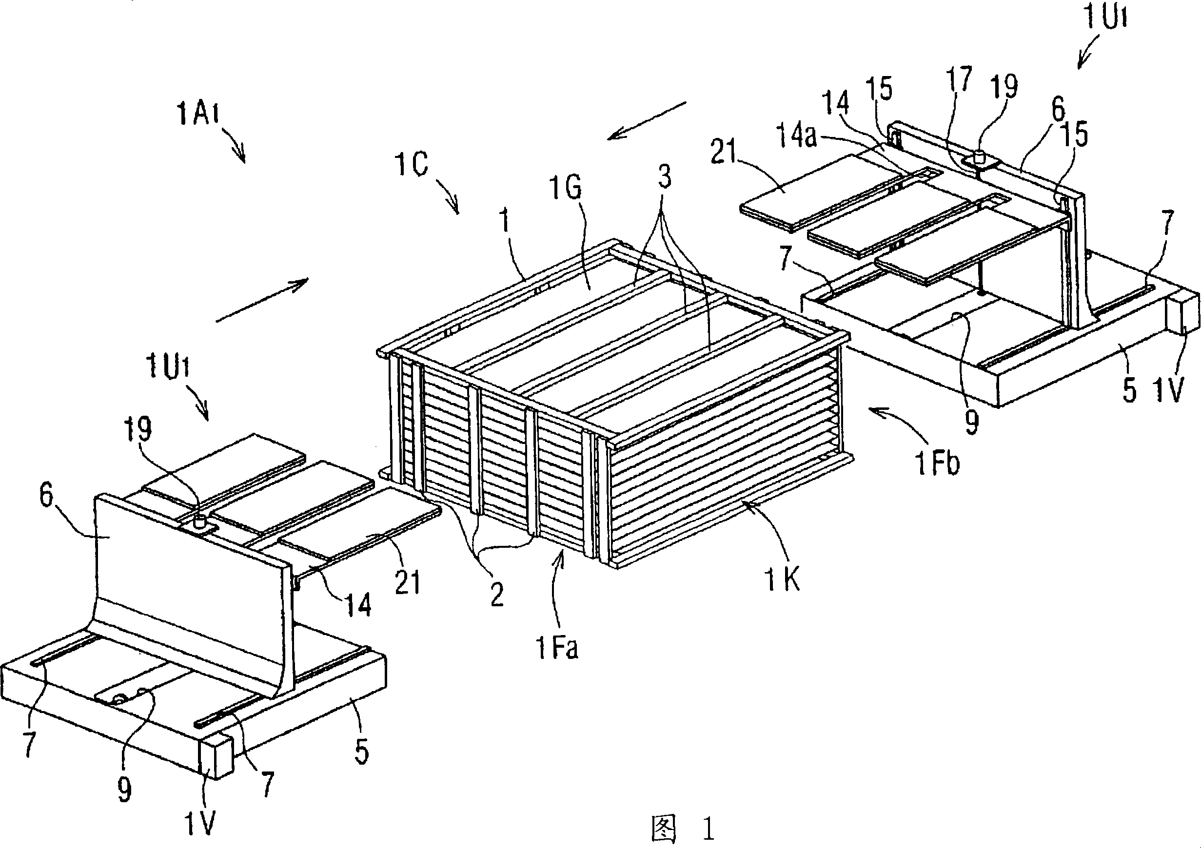
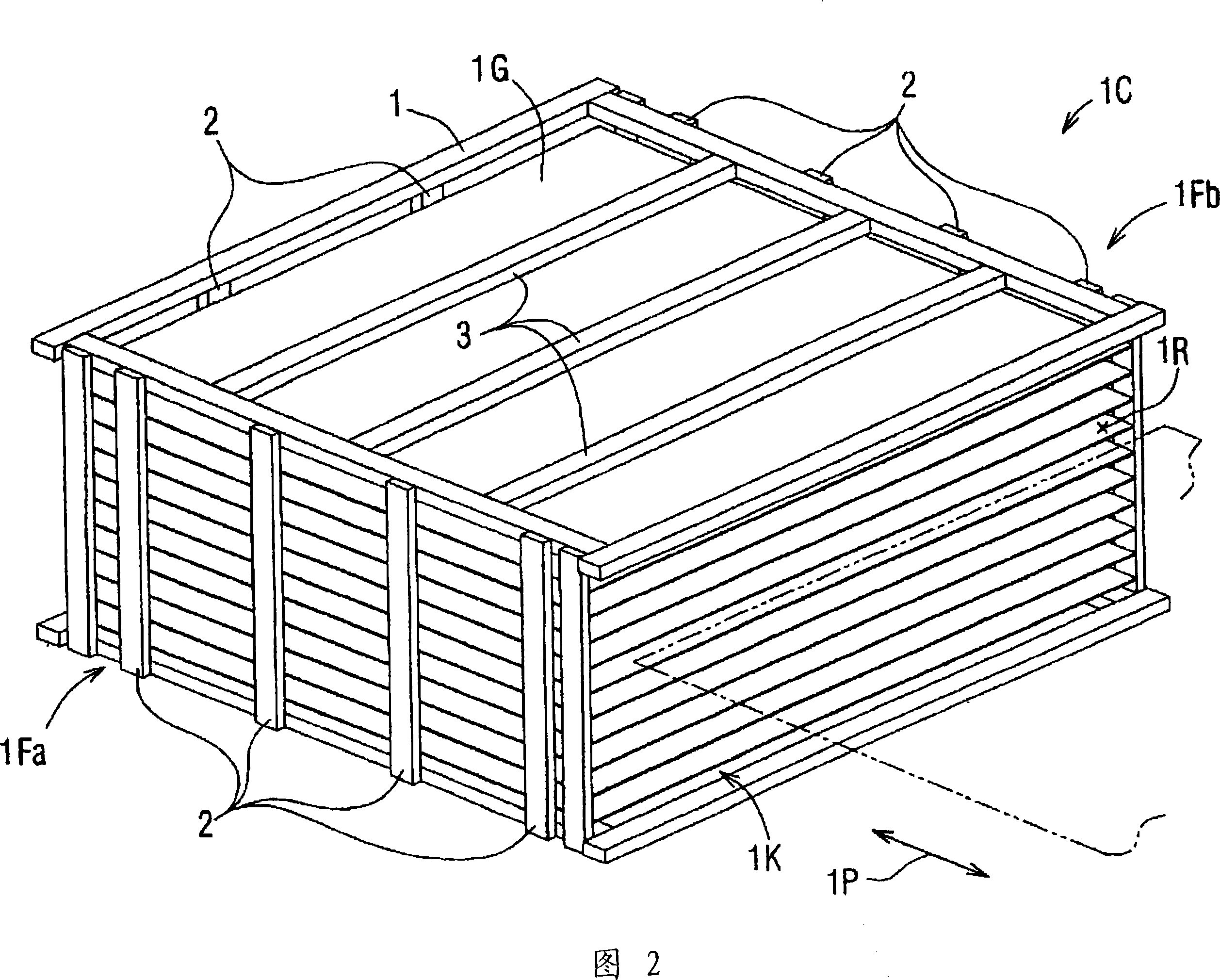
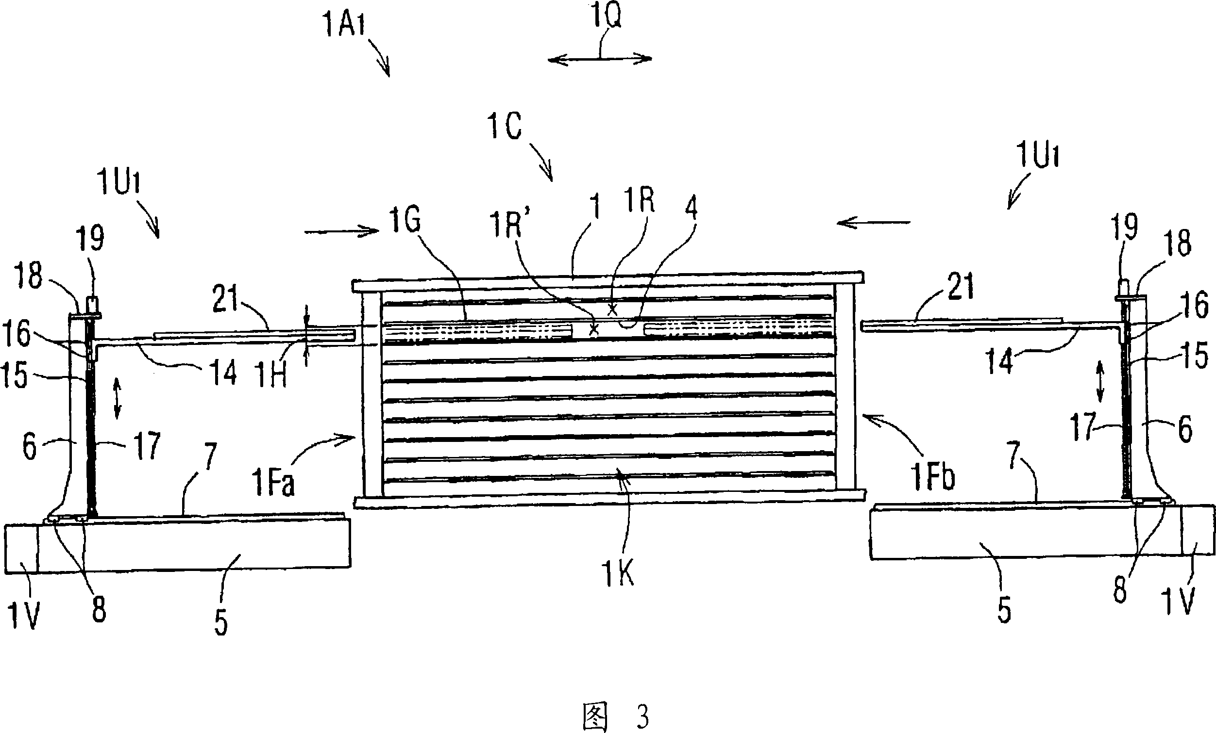
[0133] 1 is an overall perspective view of a substrate loading and unloading device 1A1 according to the first embodiment of the present invention, FIG. 2 is a perspective view of a substrate box 1C, FIG. 3 is a front view of the substrate loading and unloading device 1A1 of the first embodiment, and FIG. 4 is a pair of 5 is a plan view of the substrate take-out device 1B, and FIG. 6 is a side sectional view of the substrate take-out device 1B.

[0134] As shown in FIGS. 1 and 3 , the substrate loading / unloading apparatus 1A1 of the first embodiment includes a substrate box 1C and a pair of side surfaces 1Fa adjacent to a specific side surface (loading / unloading opening 1K) of the substrate 1G of the substrate box 1C, Each substrate elevating unit 1U1 arranged in 1Fb is constituted. A compressed air source 1V for supplying compressed air is at...

no. 2 example

[0151] The above-mentioned substrate loading and unloading apparatus 1A1 of the first embodiment is a system in which a pair of substrate elevating units 1U1 are arranged with respect to one substrate case 1C, and a method in which the substrate elevating arms 14 enter from both side surfaces 1Fa and 1Fb of the substrate case 1C, respectively. . However, as shown in FIG. 9 , a substrate loading / unloading device 1A2 composed of one substrate box 1C and one substrate elevating unit 1U2 may also be used. In the substrate loading / unloading apparatus 1A2 of the second embodiment, there is an advantage that the substrate elevating unit 1U2 is constituted by one. In addition, the substrate loading / unloading apparatus 1A2 shown in FIG. 9 is a form in which the substrate lifting arm 34 of the substrate lifting unit 1U2 enters from the side surface 1Fa of one side of the substrate box 1C. However, the elevating arm 34 may enter from the other side surface 1Fb of the substrate box 1C, t...

no. 3 example

[0153] In addition, in the substrate elevating unit 1U3 shown in FIG. In the pair of substrate elevating units 1U3 constituting the substrate loading / unloading apparatus 1A3 of the third embodiment, each air floating unit 21 is attached to each substrate elevating arm 35 , and air piping is formed so that they operate independently. road. In addition, each substrate lifting arm 35 is attached to the movable machine frame 6 in a single-arm state. And the air piping line is switched by the switching apparatus which is not shown in figure so that only the air-floating unit 21 corresponding to the specific board|substrate 1G may discharge compressed air. Then, only a specific substrate 1G floats among the substrates 1G supported in multiple stages, and this substrate 1G is carried out by the substrate take-out device 1B. Moreover, when carrying in the board|substrate 1G, pressurized air is ejected only from the air float corresponding 21 corresponding to the rack 1R which carrie...


PUM


Abstract

The invention relates to a substrate loading and unloading device, a substrate transporting method and a device thereof, which can load and unload a substrate to any rack of a substrate box. On the box body (1) constituting the substrate box (1C), the substrate (1G) stored on each rack (1R) formed with a plurality of wires (4) attached in a tensioned state as a shelf board is unloaded. In this case, each substrate lifting arm (14) constituting a pair of substrate lifting units (1U1) enters into the rack (1R') directly below the rack (1R) containing the substrate (G), and is mounted on the rack (1R') The air floating unit (21) above each substrate lifting arm (14) is operated to eject pressure air, thereby leading out the substrate (1G) in a state of being floated.

Description

[0001] This application is a divisional application of a Chinese patent application with an application date of November 04, 2004, an application number of 200480032167.0, and an invention title of "substrate loading and unloading device, substrate transportation method and device". technical field [0002] The present invention relates to an apparatus for loading and unloading substrates stored on a predetermined shelf of a substrate box. [0003] In addition, the present invention relates to a method of transporting the substrate along a processing apparatus group composed of a plurality of processing apparatuses arranged in order of the steps in order to process each step in a semiconductor manufacturing apparatus that sequentially passes through a plurality of steps to form semiconductor elements on the substrate. Methods and devices. [0004] This application is based on Japanese patent application No. 2003-376429 filed on November 6, 2003, Japanese patent application No....

Claims


Application Information

Patent Timeline
Patent Type & Authority Applications(China)
IPC IPC(8): H01L21/677B65G49/05B65G49/06B65G49/07H01L21/673H01L21/68
Inventor 北泽保良
Owner SHINKO ELECTRIC CO LTD
Why Eureka
Try Eureka