Capacitor microphone

A microphone and capacitor technology, applied in the field of capacitor microphones using semiconductor diaphragms, can solve the problems of inconsistent deformation of the central part of the diaphragm, vibration interference of diaphragm electrodes, uneven air gaps, etc., to achieve uniform gaps, increase bias, and improve sensitivity. Effect

Inactive Publication Date: 2008-05-28
YAMAHA CORP
View PDF2 Cites 16 Cited by
  • Summary
  • Abstract
  • Description
  • Claims
  • Application Information

AI Technical Summary

Problems solved by technology

This makes it easy for the air gap (formed between the diaphragm electrode and the fixed electrode) to become non-uniform, whereby the air gap may be partially reduced, thereby reducing the attractive potential energy
Such a problem poses yet another limitation on increasing the bias voltage applied to the condenser microphone
[0009] In addition, the uneven air gap and the fixation of the terminals can interfere with the vibration of the diaphragm electrode, which can cause deformation inconsistent with the central part of the diaphragm
This dissipates sensitivity and makes it difficult to predict performance in a design

Method used


Image

  • Capacitor microphone
  • Capacitor microphone
  • Capacitor microphone

Examples


no. 1 example

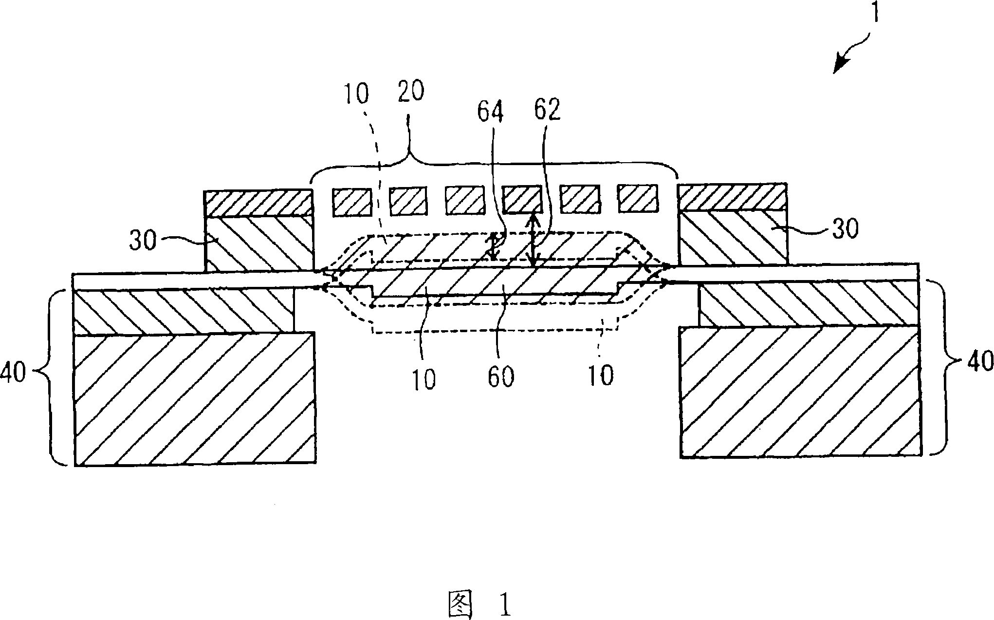
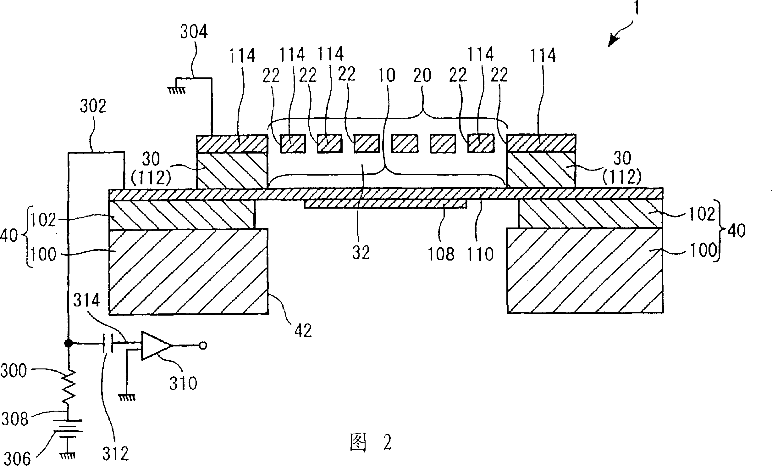
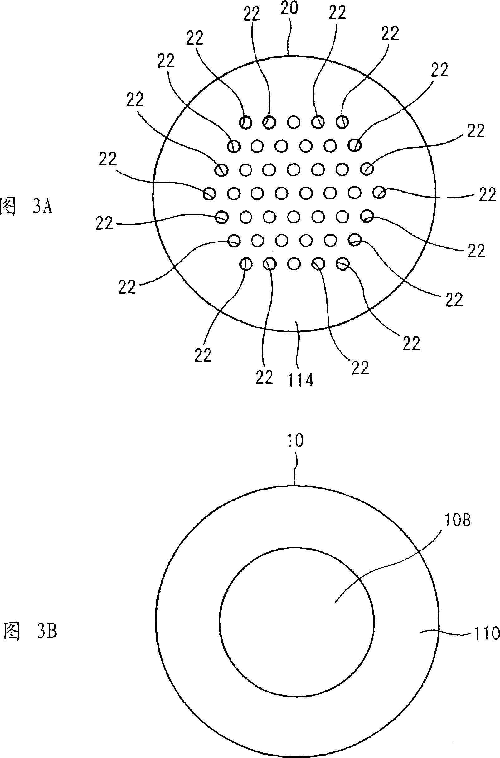
[0105] The general structure of the condenser microphone according to the first embodiment of the present invention will be described with reference to FIGS. 2 and 3A and 3B. 2 is a cross-sectional view schematically showing the structure of the condenser microphone 1; FIG. 3A is a top view of a back plate 20 included in the condenser microphone 1;

[0106] The condenser microphone 1 is called a "silicon microphone", which is produced using a semiconductor manufacturing process. As shown in FIG. 2, the condenser microphone 1 includes a sound sensing section and a detection section realized by a circuit.

[0107] (a) Structure of the sound sensing part

[0108] As shown in FIG. 2 , the acoustic sensing part of the capacitor sensor 1 includes the above-mentioned diaphragm 10 and back plate 20 , as well as a spacer 30 and a bottom 40 .

[0109] Separator 10 includes a designated portion (hereinafter referred to as non-fixed portion of conductive film 110 ) and insulating film 1...

no. 3 example

[0152] Next, a condenser microphone 3 in a third embodiment of the present invention will be described with reference to FIGS. 11A and 11B . Wherein, the central portion 14 of the diaphragm 11 has a double-layer structure including the conductive film 23 and the conductive film 110 . The conductive film 110 serves as a reinforcing film that reinforces the rigidity of the central portion 14 of the diaphragm 11 , and is formed to cover the entire central portion 14 . A plurality of proximal portions 15 are formed in the diaphragm 11 by using the conductive film 110, where they function as a bridge structure connecting the central portion 14 and the spacer 30 to each other. Each proximal portion 15 is bent and folded in a zigzag fashion to act as a spring. For this reason, the stiffness of the proximal portion 15 is significantly reduced compared to the stiffness of the central portion 14 , thereby ensuring that deformations of the diaphragm 11 that propagate the sound waves mus...

no. 4 example

[0155] 12A and 12B show a condenser microphone 4 according to a fourth embodiment of the present invention. The fourth embodiment is characterized in that a ring-shaped conductive film 24 is formed around the central portion 116 of the diaphragm 12, whereby the rigidity of the diaphragm 12 is increased.


PUM


Abstract

A capacitor microphone is constituted by a plate having a fixed electrode, a diaphragm including a center portion and at least one near-end portion that is fixed to the outer periphery, in which the center portion having a vibrating electrode, which is positioned relative to the fixed electrode and which vibrates in response to sound waves, is increased in rigidity in comparison with the near-end portion; and a spacer that is fixed to the plate and the near-end portion of the diaphragm and that has an air gap formed between the plate and the diaphragm. Alternatively, a diaphragm electrode is horizontally supported by extension arms extended from a circular plate thereof and is vertically held in a hanging state being apart from a fixed electrode with a controlled distance therebetween.

Description

[0001] technical field [0002] The present invention relates to condenser microphones, in particular to condenser microphones using semiconductor diaphragms. [0003] This application claims priority based on four Japanese patent applications, namely Patent Application No. 2005-261804 (application date: September 9, 2005), patent application No. 2006-167308 (application date: June 16, 2006), Patent application number 2006-188459 (application date: July 7, 2006), and patent application number 2006-223425 (application date: August 18, 2006), the contents of the above patent applications are hereby incorporated by reference. Background technique [0004] It is well known that the same method as that of semiconductor devices can be used to manufacture condenser microphones. A condenser microphone is designed as an electrode connecting plate and a diaphragm vibrating due to sound waves, wherein the plate and diaphragm are supported and separated from each other by insulating spac...

Claims


Application Information

Patent Timeline
Patent Type & Authority Applications(China)
IPC IPC(8): H04R19/04
Inventor 铃木幸俊铃木民人
Owner YAMAHA CORP
Why Eureka
Try Eureka