Fuel supply device

A technology of fuel supply device and drive shaft, which is applied in the direction of liquid fuel feeder, charging system, liquid variable capacity machinery, etc. It can solve problems such as fire and motor heating, and achieve the effect of reducing the number of parts and realizing miniaturization

Inactive Publication Date: 2008-06-04
MITSUBISHI ELECTRIC CORP
View PDF4 Cites 0 Cited by
  • Summary
  • Abstract
  • Description
  • Claims
  • Application Information

AI Technical Summary

Problems solved by technology

If the piston becomes self-locking, the motor will also become self-locking, and the maximum current will flow through the motor, causing the motor to heat up, and in the worst case, it will cause a fire

Method used


Image

  • Fuel supply device
  • Fuel supply device
  • Fuel supply device

Examples


Embodiment Construction
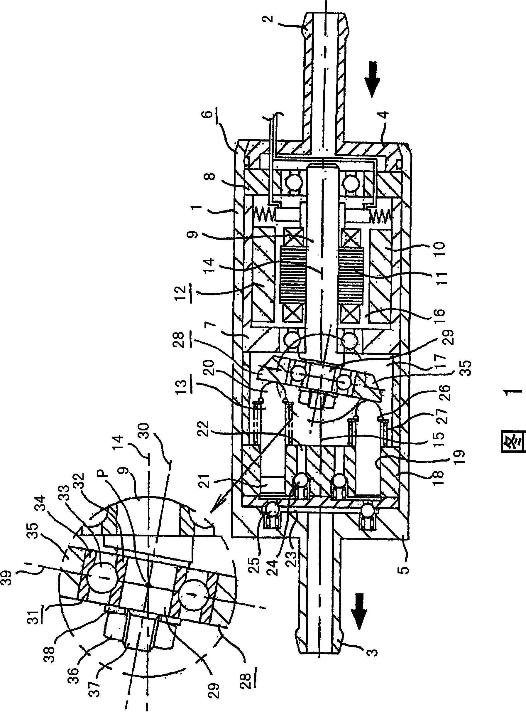
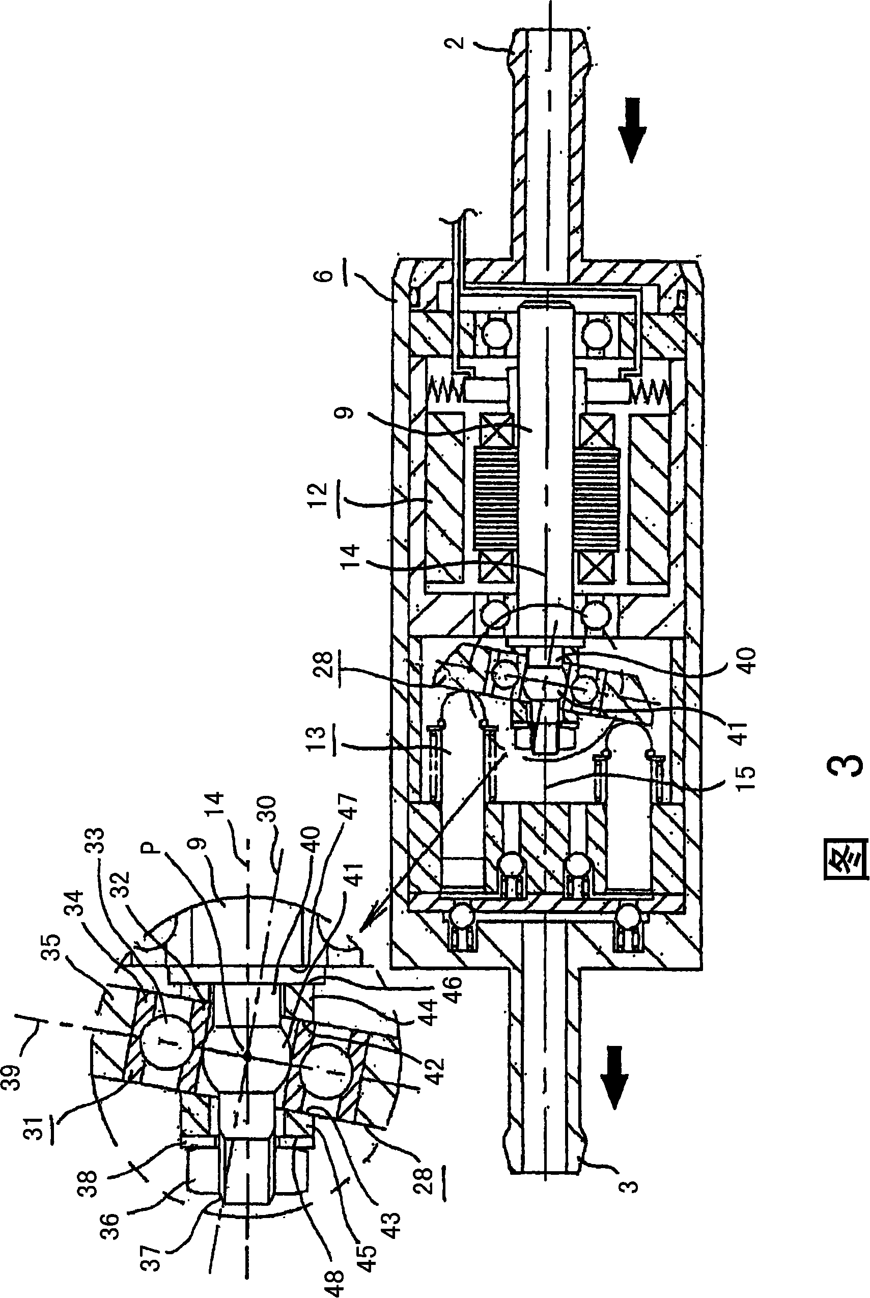
[0044] Embodiment 1

[0045] Fig. 1 is a schematic cross-sectional view showing an embodiment of the fuel supply device of the present invention, the fuel supply device shown in the figure has a hollow cylindrical shape as a whole, and has a housing 6, which includes: a cylindrical wall 1; On both ends, there are first end wall 4 and second end wall 5 with suction port 2 and output port 3 respectively. The fuel supply device also includes: the suction port 2 side in the casing 6, the drive shaft 9 supported by the bearing 7 and the bearing 8 and the motor that has the rotor 11 rotating in the stator 10, that is, the driving device 12; On the output port 3 side in the body 6 , the pump device 13 driven by the drive device 12 . The axis 14 of the drive device 12 coincides with the axis 15 of the pump device 13 .

[0046] The fuel that enters the casing 6 from the suction port 2 flows axially generally in the drive device chamber 16 in the casing 6 in which the drive device 12 ...


PUM


Abstract

The invention provides a small fuel supply device with a few amounts of elements. The rotating inclined plate of the fuel supply device is arranged by a rolling bearing whose axle center is inclined relative to a drive shaft, the axle center of the drive shaft passes trough the axle center of the rolling bearing and crossing points of planes including a plurality of centers of bearing balls. The rotating inclined plate uses the inclining support face of a bush to support the oblique of the rotating inclined plate under the state that the rotating inclined plate is inclined by that rotating inclined plate tables with the installation axis which is inclined relative to the drive shaft or tables with the ball part of the drive shaft. The rotating inclined plate can be supported by the bush across an elastic component or that the torque failure intensity of the bush is lower than self-locking torque. The invention can reduce the amount of the elements and realize the miniaturization of the fuel supply device.

Description

technical field [0001] The present invention relates to a fuel supply device for motor-driving a swash plate type axial piston pump. Background technique [0002] Due to environmental problems, the fuel supply system has been changed from a mechanical carburetor to an electronically controlled system with a fuel injection valve from the viewpoint of exhaust gas restriction and fuel cost increase. In recent years, all automobiles have adopted the latter system. In recent years, the restriction of environmental problems is not only limited to automobiles, but also gradually expanded to two-wheeled vehicles, outboard motors, and special vehicles. The fuel supply device used in automobiles is the centrifugal pump installed in the fuel tank. In-tank fuel supply devices (not shown) have become the mainstream, but a larger fuel tank is required. Due to the small fuel tank, small displacement, and installation space problems, it is impossible to arrange an in-tank fuel supply in the...

Claims


Application Information

Patent Timeline
Patent Type & Authority Applications(China)
IPC IPC(8): F04B1/16F02M37/08
Inventor 楠本教志大西善彦能濑慎也
Owner MITSUBISHI ELECTRIC CORP
Why Eureka
Try Eureka