Intelligent battery system power control method

An intelligent battery and power control technology, applied in battery circuit devices, electrical program control, secondary battery charging/discharging, etc., can solve the problems of power consumption, waste of power consumption, inability to continuously receive, etc., to achieve high battery stability, The effect of reducing power consumption and prolonging the use time

Inactive Publication Date: 2008-06-04
LEJIN ELECTRONICS KUNSHAN COMPUTER CO LTD
View PDF0 Cites 16 Cited by
  • Summary
  • Abstract
  • Description
  • Claims
  • Application Information

AI Technical Summary

Problems solved by technology

That is, although the system is in a suspended state and will not receive status reports from the smart battery, the SCM of the smart battery always maintains an active state, resulting in unnecessary power consumption
[0011] In order to avoid this situation, the SCM operation of the smart battery can be forcibly interrupted according to the system status, but at this time, the SCM and the system will never judge the abnormal operation of the battery, and the stability of the battery cannot be guaranteed.
[0012] As mentioned above, if the battery is installed in the system, but the operating state of the system is not in the off state, the SCM on the existing smart battery will maintain the active state of continuously reporting the battery status to the system, and only when the system state changes to the off state or the smart battery When it is separated from the system, it will switch to a suspended state. Therefore, when the system supports low power mode, the low power mode that cannot continue to receive smart battery status reports also has the problem of wasting power consumption due to SCM driving.
In order to prevent this, if the SCM is forcibly interrupted according to the system state, it will not be clear about the change of the battery state, and there is a problem that its stability cannot be guaranteed.

Method used


Image

  • Intelligent battery system power control method

Examples


Embodiment Construction

[0018] Embodiments of the present invention will be described in detail below with reference to the accompanying drawings.

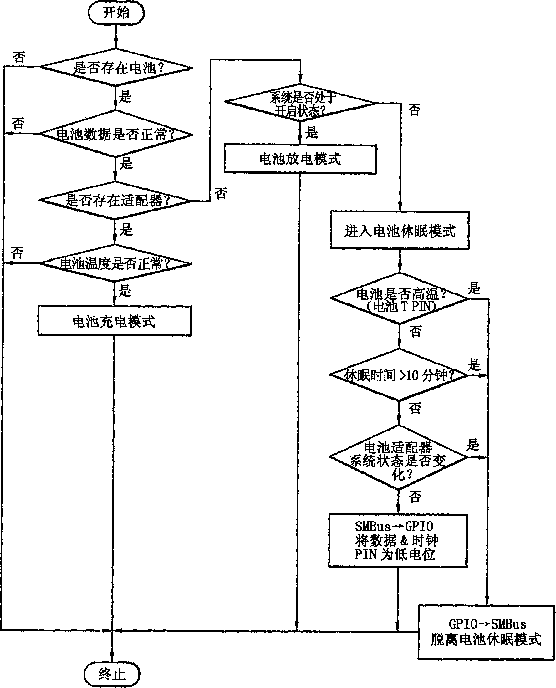
[0019] figure 1 It is a flow chart of the action process of an embodiment of the present invention. As shown in the figure, a new action mode of the battery sleep mode is proposed.

[0020] The smart battery configuration proposed by the present invention to support the battery sleep mode includes: according to the smart battery regulations, measure and calculate the battery temperature, battery remaining power, charge / discharge current, voltage, etc., and report the battery power measurement to the system through SMBus IC; the 1st and 2nd circuit parts that stop charging and discharging in order to protect the battery according to the control of the above-mentioned battery power measurement IC and the abnormal condition of the battery; the thermistor that is connected to the above-mentioned battery power measurement IC and measures the battery temperatu...


PUM


Abstract

The invention relates to a power control method for a system adopting a smart battery. When the system adopting the smart battery in the invention is in a non-opening state, communications PIN voltage of the smart battery is forced to be converted, thus converting the smart battery into a sleep mode; to protect the stability of the battery, the system periodically monitors the temperature output PIN of the smart battery and finishes the sleep mode at a certain time periodically; after the battery information is renewed and monitored, the battery is converted into the sleep mode again. Therefore, the smart battery and the action state of the system are reactive with each other, thus reducing unnecessary electricity consumption, guaranteeing high stability of the battery and presenting the effect of prolonging service time of the system.

Description

technical field [0001] The present invention relates to a power supply control method for a system using an intelligent battery, in particular to a system using an intelligent battery that can minimize the power consumption of an intelligent protection module inserted into an intelligent battery pack and protect the stability of the battery according to the operating mode of the system The system's power control method. Background technique [0002] Recently, various portable devices such as portable terminals, camcorders, digital cameras, notebook computers, PDAs, wireless TVs, web pads (Web Pads), and smart displays have shifted from voice-based to video, data-based, and so on. , e-mail and other multimedia use, its power consumption has increased dramatically. For this reason, a battery device capable of satisfying larger capacity and repeated charging and discharging is required. [0003] At present, rechargeable battery companies such as lithium-ion batteries and lith...

Claims


Application Information

Patent Timeline
Patent Type & Authority Applications(China)
IPC IPC(8): H01M10/44H02J7/00G05B19/04
CPCY02E60/12Y02E60/10
Inventor 洪淳学
Owner LEJIN ELECTRONICS KUNSHAN COMPUTER CO LTD
Why Eureka
Try Eureka