Advanced chemical mechanical polishing system with smart endpoint detection

A boundary point and workpiece fixture technology, applied in grinding/polishing equipment, control of workpiece feed motion, manufacturing tools, etc., can solve problems such as difficulty in reducing thickness and plane shape, and achieve optimization of polishing, saving time and cost. Effect

Inactive Publication Date: 2008-06-04
ASM NUTOOL
View PDF2 Cites 19 Cited by
  • Summary
  • Abstract
  • Description
  • Claims
  • Application Information

AI Technical Summary

Problems solved by technology

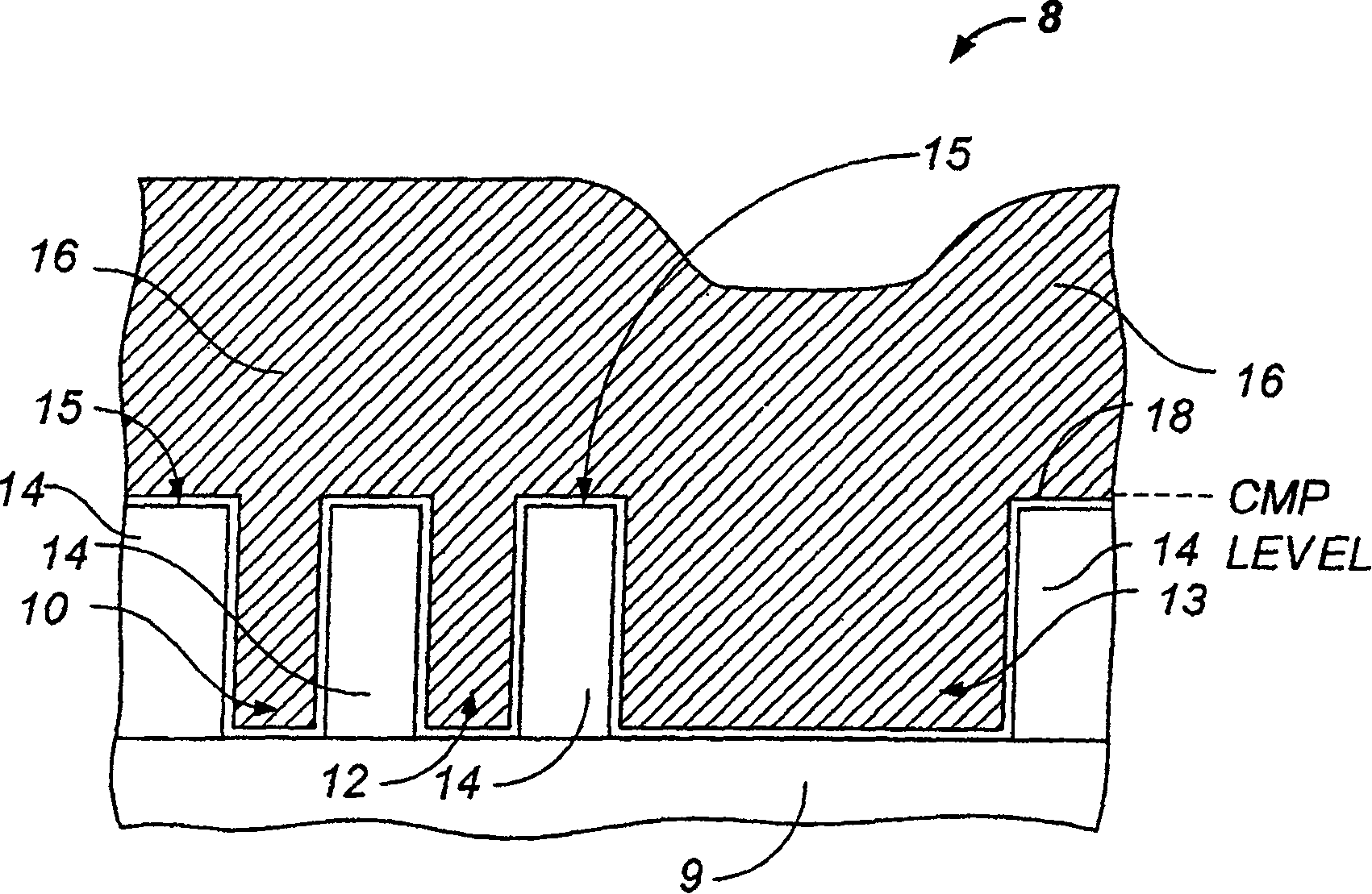
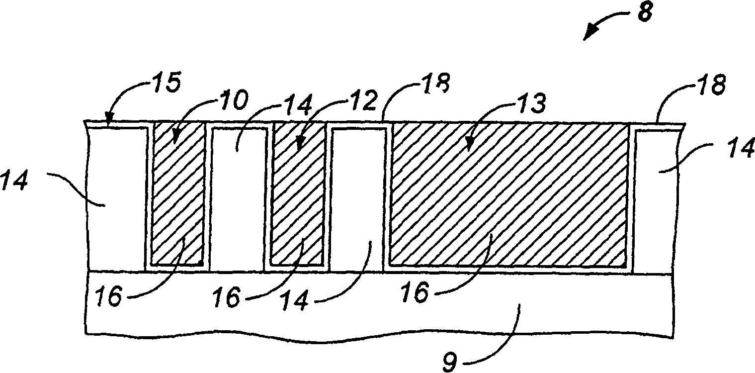
[0015] Problems with current STI technology include difficulty in measuring silicon dioxide thickness by optical interferometry because the thickness measurement signal periodically repeats itself as the silicon dioxide thickness increases or decreases
[0016] Another problem with the prior art is

Method used


Image

  • Advanced chemical mechanical polishing system with smart endpoint detection
  • Advanced chemical mechanical polishing system with smart endpoint detection
  • Advanced chemical mechanical polishing system with smart endpoint detection

Examples


Example Embodiment

[0067] As described below, the present invention provides a method and system for in-situ boundary point detection using a material removal method such as CMP. The description is given below with reference to the drawings, and the same reference numerals in the drawings represent the same components.

[0068] A. Boundary point detection system

[0069] figure 2 An exemplary chemical mechanical polishing (CMP) apparatus 100 is shown, which includes a polishing element 102 and a carriage 104. The polishing element can be a polishing belt, a polishing pad, or other types of polishing elements. The polishing element 102 includes an upper or processed surface 106 and a bottom surface 108. The bottom surface 108 of the polishing element is tensioned on a support plate 109 such as a pressing plate. The polishing element and the bracket are arranged such that the surface of the workpiece abuts the polishing element, that is, the surface of the workpiece can be very close to or contact t...


PUM


Abstract

An apparatus for polishing a workpiece includes a workpiece holder 104 configured to hold the workpiece, a polishing member 102 configured to be positioned adjacent to a face of the workpiece in order to polish the workpiece face with a front side of the polishing member, and a platen 600 having a plurality of pressure zones zl-z4 configured to selectively apply pressure to the polishing member thereby causing the polishing member to contact the workpiece face with selective pressure. In another embodiment, the apparatus includes a pressure controller 564 coupled to the platen and configured to selectively adjust the pressure zones zl-z4.

Description

[0001] This application is U.S. Patent Application Serial No. 10 / 321,150 (NT-280-US), filed December 17, 2002, and U.S. Patent Application Serial No. 10 / 105,016 (NT-250-US), filed March 22, 2002 , Continuation of U.S. Patent Application Serial No. 10 / 197,090 (NT-248-US), filed July 15, 2002, and U.S. Patent Application Serial No. 10 / 052,475 (NT-238-US), filed January 17, 2002 application, which is hereby incorporated by reference in its entirety. [0002] This application claims the benefit of U.S. Provisional Patent Application Serial No. 60 / 436,706 (NT-278-P4) filed December 27, 2002, U.S. Provisional Patent Application Serial No. 60 / 436,108 (NT-278) filed December 23, 2002 -P3), U.S. Provisional Patent Application Serial No. 60 / 417,544 filed October 10, 2002 (NT-278-P2), U.S. Provisional Patent Application Serial No. 60 / 415,579 filed September 27, 2002 (NT-278 -P), U.S. Provisional Patent Application Serial No. 60 / 397,110 (NT-273-P), filed July 19, 2002, U.S. Provisional Pat...

Claims


Application Information

Patent Timeline
IPC IPC(8): B24B1/00B24B49/02B24B49/12B24B49/16H01L21/302
Inventor 王雨春伯纳德·M·弗雷布伦特·M·巴索尔霍马扬·塔里道格拉斯·扬布雷特·E·迈克格拉特穆克施·德赛艾弗莱恩·维拉兹奎兹
Owner ASM NUTOOL
Why Eureka
Try Eureka