
Lip type seal

A technology for sealing fluid and lips, applied in the direction of engine sealing, engine components, mechanical equipment, etc., can solve the problems of reduced sealing performance, poor creep characteristics, damage, etc., and achieve the effect of improving sealing performance

Inactive Publication Date: 2008-06-04
NOK CORP
View PDF2 Cites 4 Cited by
  • Summary
  • Abstract
  • Description
  • Claims
  • Application Information

AI Technical Summary

Problems solved by technology

However, since the lip seal 101 is made of resin, the plate-shaped lip 105 has a disadvantage in that the interference is low and the sealing performance is reduced due to the inherently poor creep characteristics of the resin.
That is, the plate-shaped lip 105 is sealed by the reaction force generated by bending around the point A, so there is a risk of stress concentration at the point A and damage. Disadvantages resulting in reduced interference
Furthermore, when compared with lip seals using rubber materials, etc., the resin lacks elasticity, so it has the disadvantages of poor adhesion to the shaft and poor sealing performance.
[0004] In the following patent documents, the oil seal fixed on the back-up ring is disclosed, and the technical feature of forming a zigzag pattern on the lip is disclosed, but the lip seal made of resin is not disclosed.

Method used


Image

  • Lip type seal
  • Lip type seal
  • Lip type seal

Examples


Embodiment Construction

[0043] The preferred embodiments of the present invention will be illustrated below with reference to the accompanying drawings. However, unless the scope of the present invention is particularly limited, it is not limited to the content described in this embodiment.

[0044] The lip seal according to the embodiment of the present invention is provided in the annular space between the bracket and the shaft.

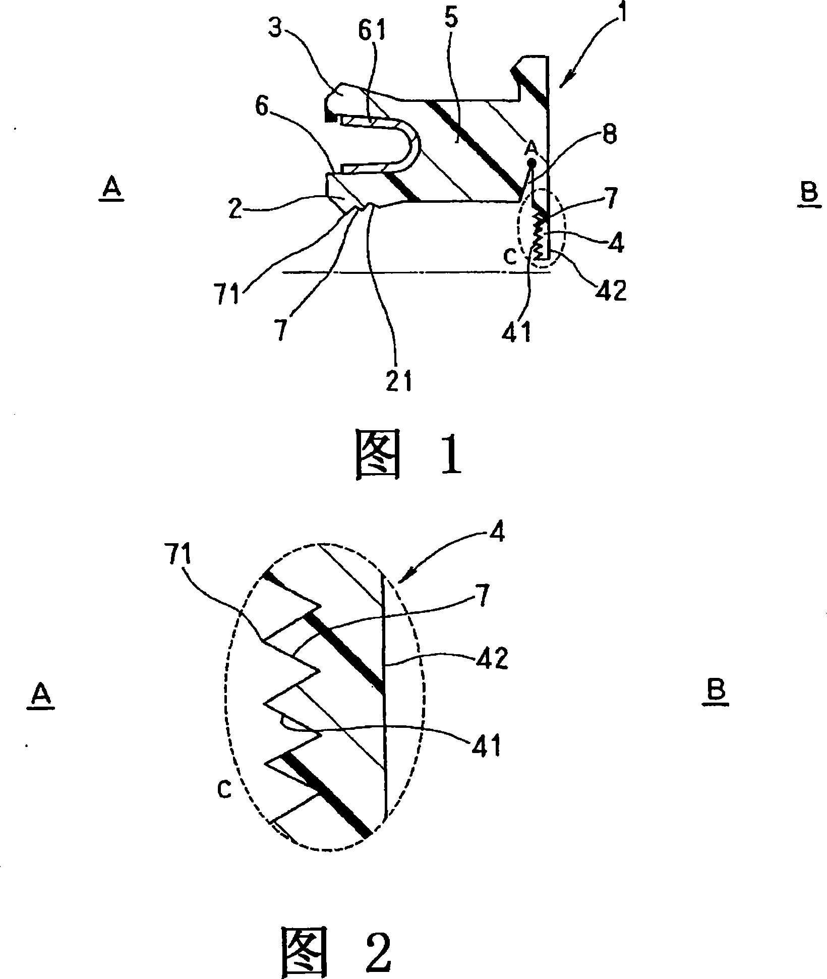
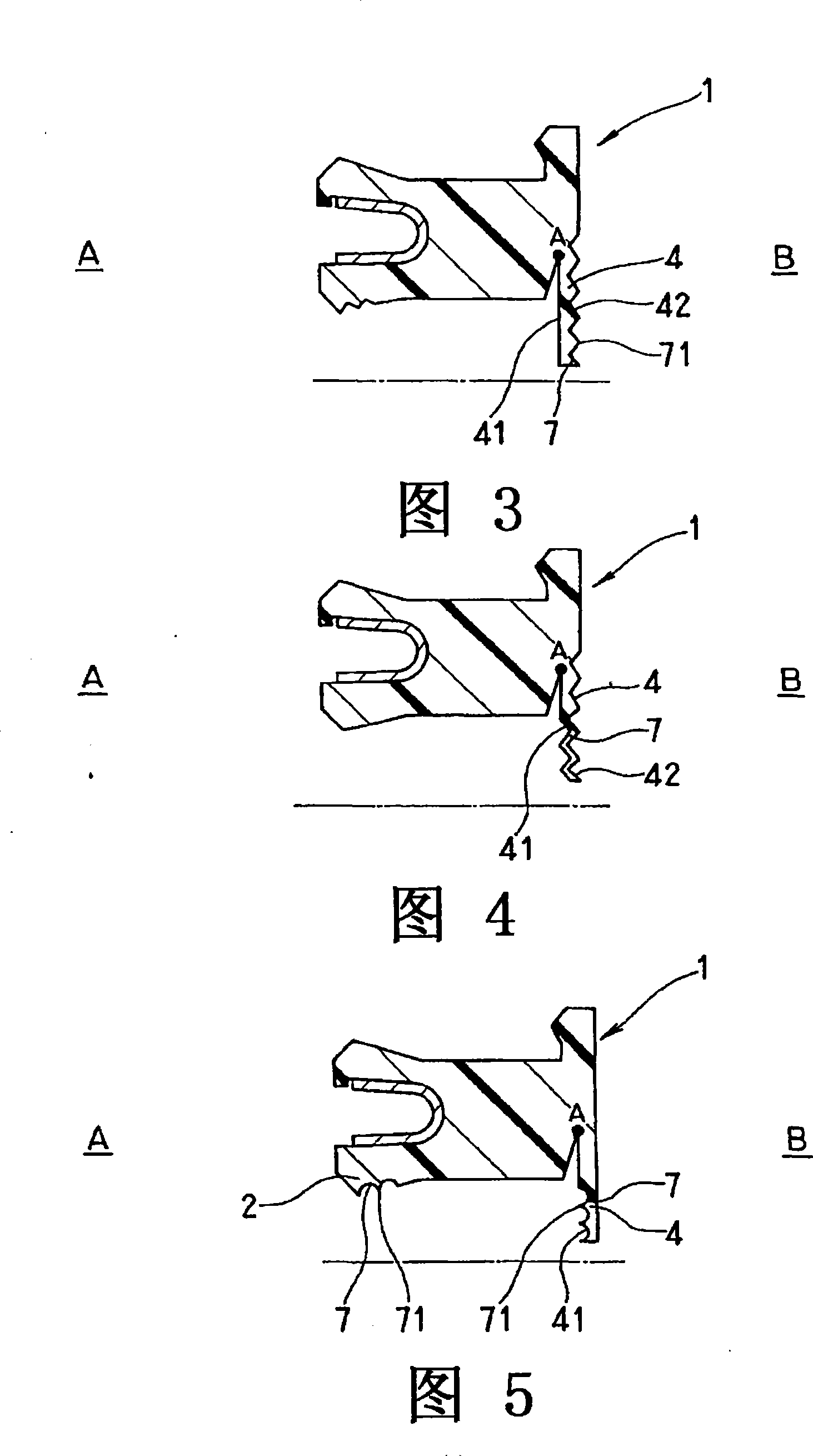
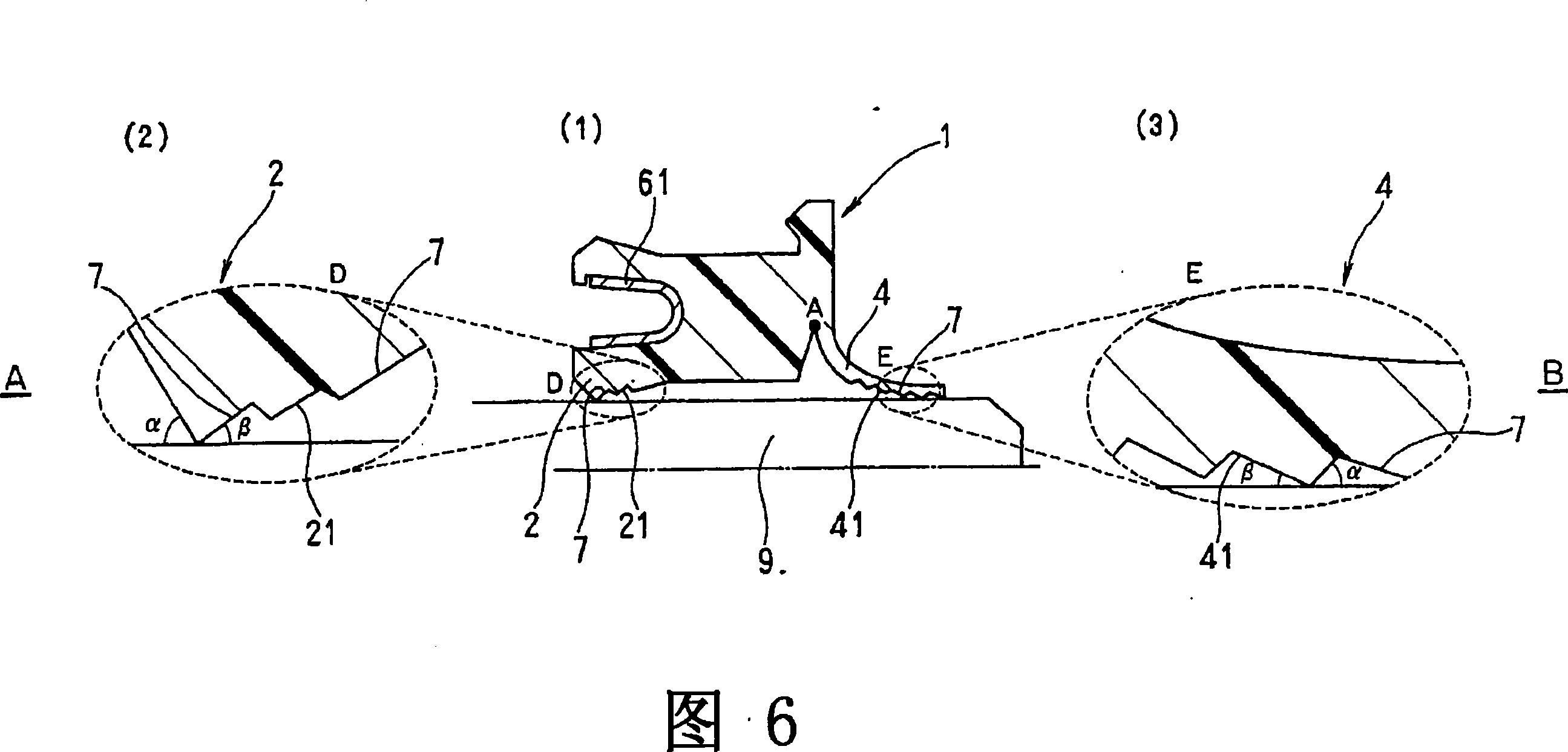
[0045] As shown in Fig. 1, the lip seal 1 according to Embodiment 1 of the present invention includes a sealing body 5 made of resin PTFE and a spring 61 installed in a cylindrical recess 6 with a U-shaped cross section; The body 5 is integrally formed by the following parts: the inner peripheral lip 2 and the outer peripheral lip 3, having a substantially cylindrical recess 6 facing the opening of the first sealing fluid side A, and being arranged on the inner and outer peripheries of the cylindrical recess 6 , in sliding contact with the shaft and the bracket; the plat...


PUM


Abstract

A resin lip type seal (1) capable of increasing safety against rupture by reducing the rigidity of a plate-like lip (4) bent about the tip point A of a roughly wedge-shaped recessed part (8) to reduce stress concentration at the point A, suppressing the lowering of sealability due to a reduction in the creep of the lip, and increasing the follow-up capability of the lip to the eccentricity of its axis. Slits are formed in the slidable contact surface (41) of the plate-like lip (4) or / and the anti-slidable contact surface (42) thereof. Slits (7) are also formed in the sloped slidable contact surface (21) of the inner lip (2) of the seal. Then, the ratio of the portion of each of the slidable contact surfaces where the slits (7) are formed is set to 1 / 2 or more of each of the surface areas of the slidable contact surfaces (21, 41, 42).

Description

technical field [0001] The invention relates to a lip seal made of resin such as PTFE which can be used for sealing a high-pressure fuel pump gasoline direct injection engine injection pump and other oil pressure, air pressure and water pressure machines. Background technique [0002] As the performance of injection pumps for gasoline direct-injection engines increases, the requirements for the operating environment of the double-fluid seal that seals the gasoline and engine oil used in the plunger portion of the pump tend to become increasingly strict. As seals, improvements in pressure resistance and chemical resistance against low-quality fuels are required, and studies have been made to switch from conventional oil seals to lip seals made of resin such as PTFE. [0003] As shown in FIG. 7 , a conventional lip seal 101 is integrally formed of an inner peripheral lip 103, an outer peripheral lip 104, and a plate-shaped lip 105 using resin; wherein, the inner peripheral lip...

Claims


Application Information

Patent Timeline
IPC IPC(8): F16J15/32F16J15/3228F16J15/3232F16J15/3236
CPCF16J15/3236F16J15/3228F16J15/3244F16J15/32
Inventor 近藤洋介田边靖章中山纯一稻村民雄水野谷弘一大谷刚生滨本耕吉
Owner NOK CORP
Learn More