Fluidized bed combustion device with wall surface-center combined supplying secondary air
A technology of combustion device and secondary air, which is applied to fluidized bed combustion equipment, fuel burning in a molten state, combustion method, etc., can solve the problem of poor operation stability of combustion device, affecting boiler combustion efficiency, and weak secondary air penetration ability. and other problems, to achieve the effect of solving the lack of secondary air penetration, promoting full mixing and reaction, and reducing uneven distribution
- Summary
- Abstract
- Description
- Claims
- Application Information
AI Technical Summary
Problems solved by technology
Method used
Image
Examples
specific Embodiment approach 1
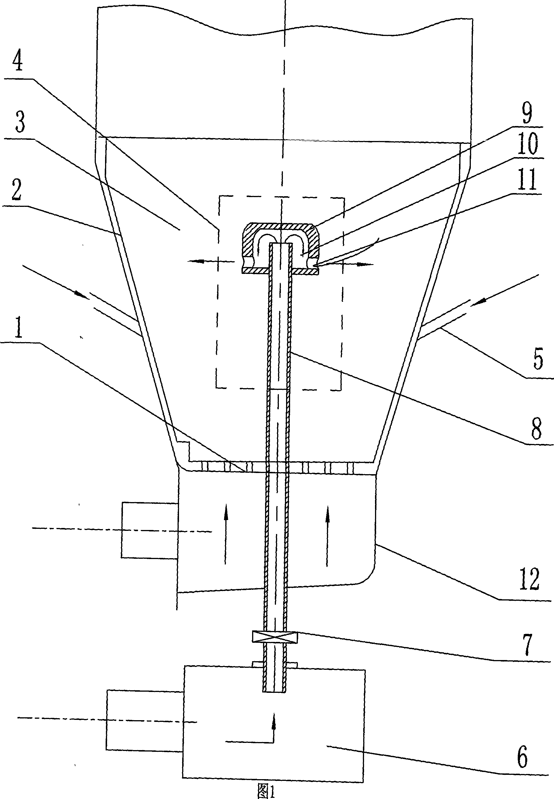
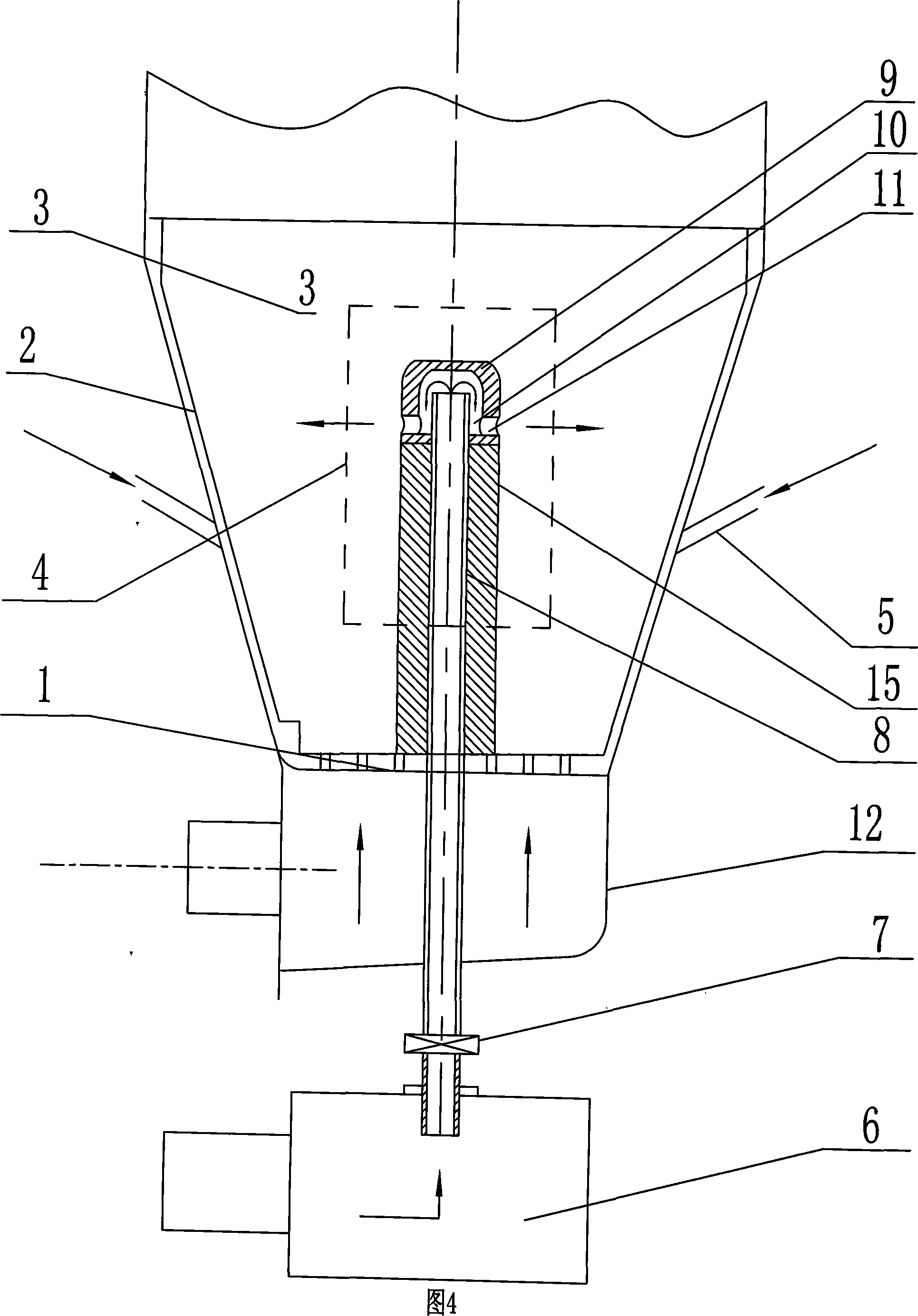
[0007] Embodiment 1: As shown in Figures 1 to 3, the wall-center fluidized bed combustion device for secondary air composite supply in this embodiment consists of a fluidized bed combustion chamber 3, an air distribution plate 1, and several downward-inclining two The secondary air duct 5 is composed of a counterflow secondary air column 4 and a secondary air box 6. The several downward-inclining secondary air ducts 5 are installed on the wall 2 of the fluidized bed combustion chamber 3, and the air distribution plate 1 Horizontally arranged at the bottom of the fluidized bed combustion chamber 3, the counterflow secondary air column 4 is arranged in the central area of the fluidized bed combustion chamber 3, and the countercurrent secondary air column 4 is mainly transported by the secondary air The pipe 8 and the counter-flow type column head 9 are composed of a secondary air nozzle 11 on the side wall of the counter-flow type column head 9. It is fixedly connected with th...
specific Embodiment approach 2
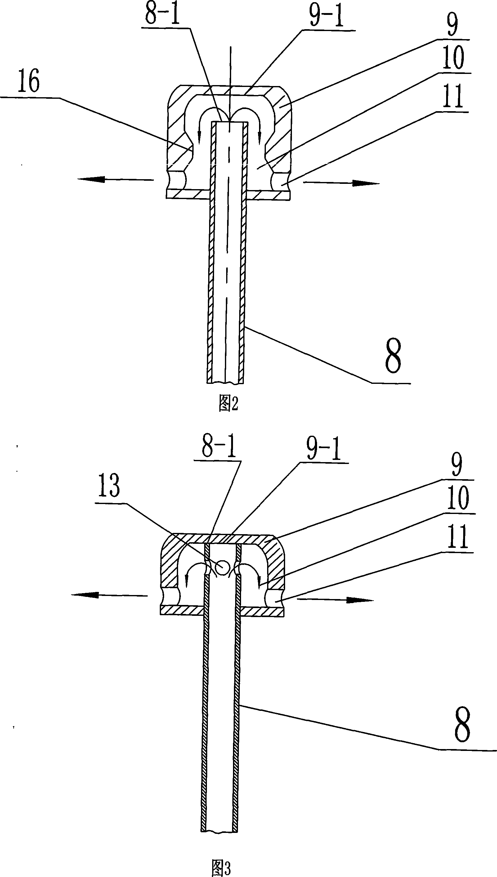
[0008] Embodiment 2: As shown in FIG. 2 , there is a gap between the upper end surface 8 - 1 of the secondary air conveying pipe 8 in this embodiment and the upper inner wall surface 9 - 1 of the counterflow column head 9 . The secondary air from the secondary air box 6 flows out through the upper end of the secondary air conveying pipe 8 into the guide air duct 10 , and then is ejected from the secondary air nozzle 11 . Other components and connections are the same as those in the first embodiment. Since the present invention (column-type countercurrent type secondary air column) is located in the high-temperature and high-concentration area of the dense phase area at the bottom of the fluidized bed, if no refractory and wear-resistant materials are laid, both the secondary air delivery pipe 8 and the counterflow type column head 9 need to adopt heat-resistant Made of wear-resistant material.
specific Embodiment approach 3
[0009] Specific embodiment three: As shown in Figure 3, the upper end surface 8-1 of the secondary air conveying pipe 8 described in this embodiment is airtightly connected with the upper end inner wall surface 9-1 of the counter-flow type column head 9, and the upper end surface 9-1 of the counter-flow type column head Several flow holes 13 are provided on the upper end sidewall of the secondary air conveying pipe 8 inside 9 . The secondary air from the secondary air box 6 passes through the secondary air conveying pipe 8 , flows out from a plurality of flow holes 13 , and then sprays out from the secondary air nozzle 11 . Other components and connections are the same as those in the first embodiment.
PUM
 Abstract
Description
Claims
Application Information
 - R&D
- Intellectual Property
- Life Sciences
- Materials
- Tech Scout
- Unparalleled Data Quality
- Higher Quality Content
- 60% Fewer Hallucinations
Browse by: Latest US Patents, China's latest patents, Technical Efficacy Thesaurus, Application Domain, Technology Topic, Popular Technical Reports.
© 2025 PatSnap. All rights reserved.Legal|Privacy policy|Modern Slavery Act Transparency Statement|Sitemap|About US| Contact US: help@patsnap.com


