LCD panel with touch control function

A technology of liquid crystal display panel and touch function, which can be used in static indicators, optics, instruments, etc., and can solve the problem that signals cannot be synchronized.

Active Publication Date: 2010-08-11
HANNSTAR DISPLAY CORPORATION
View PDF0 Cites 0 Cited by
  • Summary
  • Abstract
  • Description
  • Claims
  • Application Information

AI Technical Summary

Problems solved by technology

[0007] The purpose of the present invention is to provide a liquid crystal display panel with a touch function, which includes a switch element to control the light sensing signal transmitted by the reading line and the fan-out line to enter the signal processor, so as to solve the problem of gate-in and gate- The problem that the signal of end cannot be synchronized

Method used


Image

  • LCD panel with touch control function
  • LCD panel with touch control function
  • LCD panel with touch control function

Examples


Embodiment Construction

[0036] Without limiting the spirit and scope of application of the present invention, the implementation of the present invention is described below with multiple embodiments; those skilled in the art, after understanding the spirit of the present invention, can apply the liquid crystal display structure of the present invention to various LCD monitors.

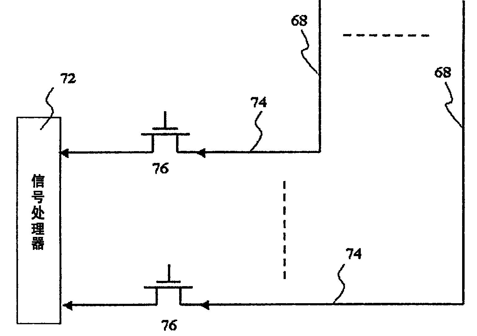
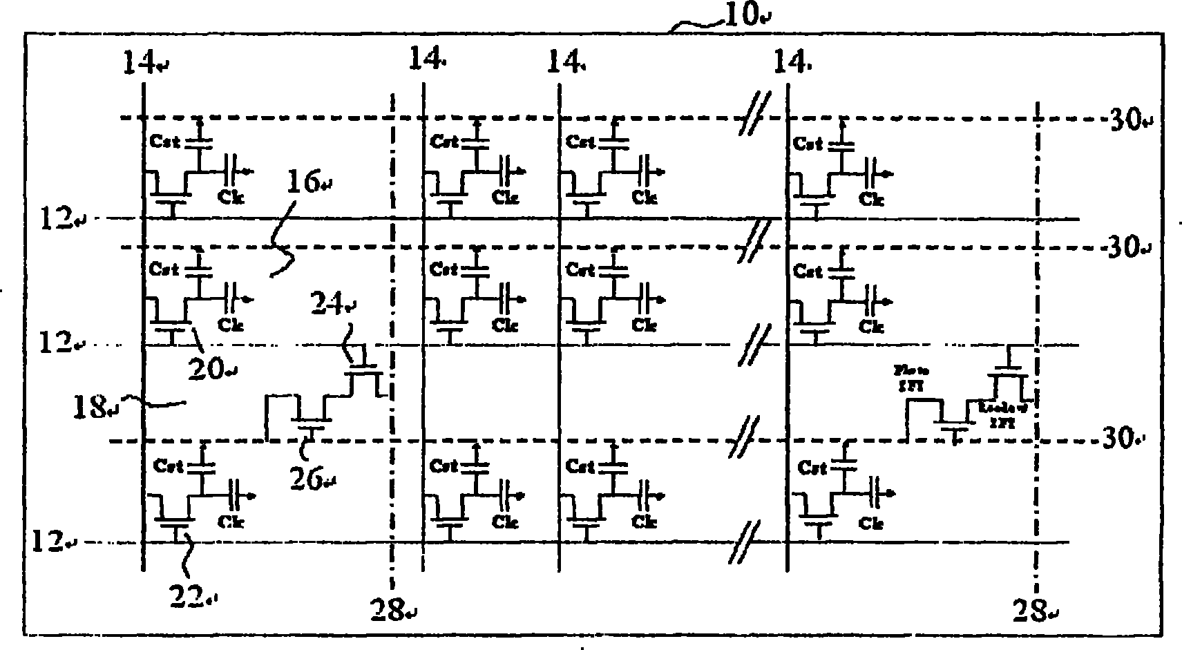
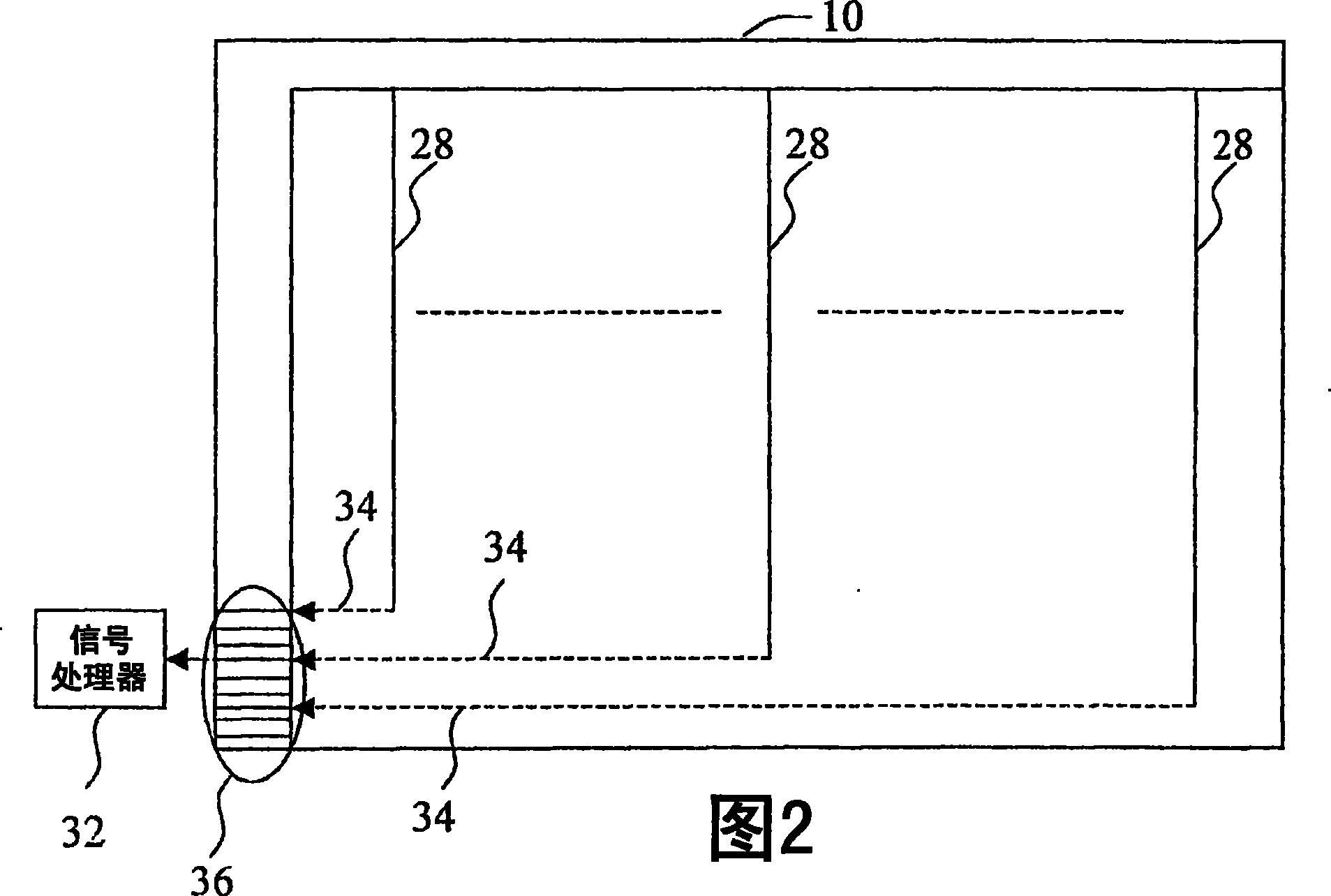
[0037] FIG. 3 is a schematic diagram of a liquid crystal display panel with a touch function according to the present invention. As shown in FIG. A pixel 56 and a second pixel 58 are respectively surrounded by two adjacent scan lines 52 and two adjacent data lines 54 . The first pixel 56 includes a first thin film transistor 60, with a gate electrically connected to the two adjacent scan lines, a source electrically connected to the two adjacent data lines, and a drain connected to the pixel electrode (not shown). As shown in FIG. 3 ), when the first thin film transistor 60 is turned on, the data voltage transmitted by the d...


PUM


Abstract

An LCD panel with touch function is provided, which comprises a plurality of scanning beams set along the horizontal direction and a plurality of date wires set along the vertical direction, as well as the first and the second pixels which are separately enclosed by two adjacent scanning beams and two adjacent data wires. The first pixel comprises the first sistor while the second pixel comprisesthe second and the third sistor. The grids of the second and the third sistors are respectively electrically connected with two adjacent scanning beams; the source electrode of the second sistor is electrically connected with a photoreceptor; the drain electrode of the second sistor is electrically connected with the reading wire; the reading line is set along the vertical direction, and one end of which is electrically connected with switching element and signal processor.

Description

technical field [0001] The invention relates to a liquid crystal display panel, in particular to a liquid crystal display panel with a touch function. Background technique [0002] Currently common touch panels (touch panels) can be classified into resistive, electromagnetic, and capacitive according to their working principles. The application range of resistive touch panels is limited to small-area products. Electromagnetic touch panels use electromagnetic induction or electromagnetic transmission and reception to locate the corresponding plane position of the contact point, while capacitive touch panels use The capacitive sensing method senses the coordinates of the contact point, that is, the contact point coordinates are obtained by using the contact point to induce capacitance changes on the opposite area of ​​the panel. [0003] Since it is known that the touch panel and the liquid crystal display panel are manufactured separately, and then assembled together, the to...

Claims


Application Information

Patent Timeline
Patent Type & Authority Patents(China)
IPC IPC(8): G02F1/13G02F1/1362G09G3/36G06K11/06
Inventor 施博盛潘轩霖
Owner HANNSTAR DISPLAY CORPORATION
Why Eureka
Try Eureka