Structure of truss-string cantilever as well as uses and construction method thereof

A cantilever beam and string cable technology, which is applied in building components, building structures, roofs, etc. to reduce impact damage and achieve self-protection effects.

Inactive Publication Date: 2008-06-18
ZHEJIANG BADA CONSTR GRP
View PDF0 Cites 5 Cited by
  • Summary
  • Abstract
  • Description
  • Claims
  • Application Information

AI Technical Summary

Problems solved by technology

Therefore, at present, there is no ideal string beam structure for the canopy structure of large stadiums.

Method used


Image

  • Structure of truss-string cantilever as well as uses and construction method thereof
  • Structure of truss-string cantilever as well as uses and construction method thereof

Examples


Embodiment 1

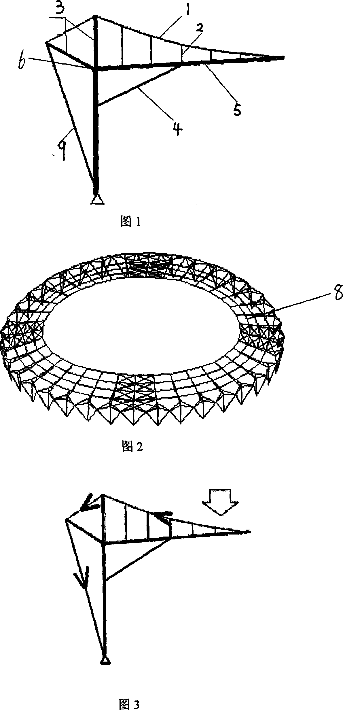
[0025] As shown in Figure 1, a string tension cantilever beam structure provided by the present embodiment includes a cantilever beam 5 and a compression bar 3, an upper string 1 and a vertical bar 2 are arranged on the cantilever beam 5, and a cantilever beam 5 bottom is provided with Stabilizing cable 4 constitutes a single string cantilever beam structure 7 thus. The end of the cantilever beam 5 is provided with a bearing 6, and the end of the cantilever beam 5 and the bearing 6 are connected by a hinged bearing.

Embodiment 2

[0027] The string tension cantilever beam structure provided in this embodiment is a prestressed structure, which needs to rely on the prestress of the upper string 1 and the stabilizing cable 4 to reach the final forming state. Therefore, as shown in Figure 2, combined with the specific characteristics of the structure, the single cantilever beams 7 can be arrayed along the ring direction and connected by ring beams 8 to form a canopy structure. The above string cantilever beam structure is applied to the canopy structure of the stadium. When being used to build a canopy structure composed of multiple stringed cantilever beams, the construction method of a stringed cantilever beam structure is to first install the cantilever beam 5, the vertical bar 2, the pressure bar 3 and the upper string cable 1 according to the The formed dimensions are made and installed in place; then the ring beams 8 are used to connect each string cantilever beam structure 7 together to form a whole;...

Embodiment 3

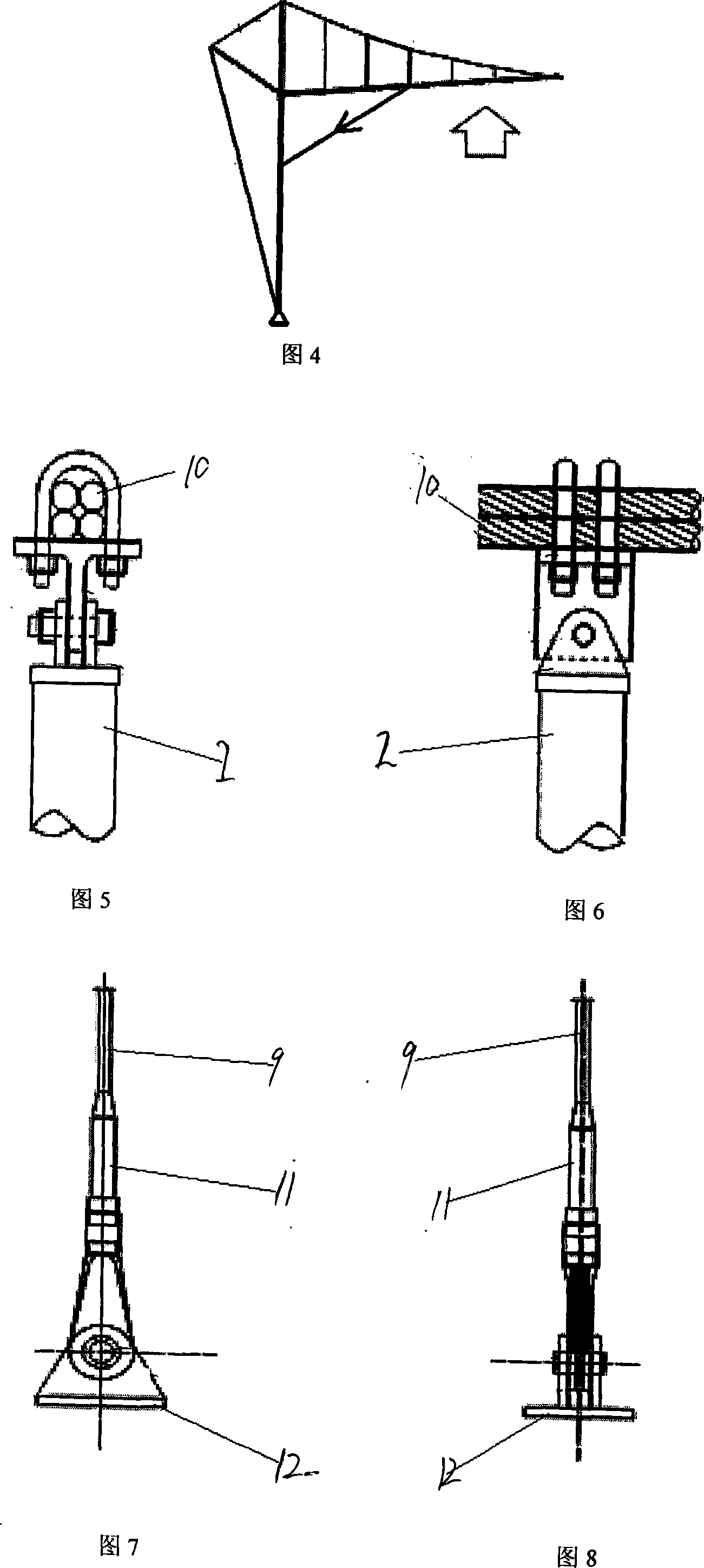
[0032] Fig. 5 and Fig. 6 are diagrams of connection nodes between the upper chord cable 1 and the vertical bar 2 or pressure bar 3, as shown in Fig. To make the tensioning adjustment of the dragline multiple times, the present invention adopts double-layer PE anti-corrosion steel wire 10. The joint adopts the combination of hot cast anchor and cold cast anchor. At the same time, a cable length adjusting device 11 is set in the cable to adjust the tension value of the cable. The cable length adjusting device 11 is a steel sleeve for adjusting the cable length. Its main node forms are shown in Figure 5, Figure 6, Figure 7, and Figure 8. Fig. 7 and Fig. 8 are connection node diagrams of the rear cable 9 and the ground anchor; when the stabilizing cable 4 is connected with the cantilever beam 5 or column, the connector 12 is embedded in the beam or column first, and then the node connection form is basically the same as that in Fig. 8 .

[0033] The structure of the present inven...


PUM


Abstract

The present invention discloses a beam string structure and an application and construction method thereof, the beam string structure comprises a cantilever 5 and a strut bar 3, the cantilever is provided with an upper cable 1 and vertical bars 2, a steadying cable 4 is arranged under the cantilever, and therefore a single-frame beam string structure 7 is formed. A bearing 6 is arranged on the end of the cantilever, which is connected with the bearing by a hinged shoe. The beam string structure provided by the present invention can array the single-frame beam string structures along an annular direction, which are connected together by ring beams to form a cantilever roof structure. The beam string structure is applied to the cantilever roof structure of a stadium. The beam string structure provided by the present invention has three advantages: (1) the one-end constraint can be realized, so that the present invention can be applied to the cantilever roof structure of the stadium; (2) the components mainly bear axial force, thus sufficiently exerting the strength of materials; (3) the structure has functions of self regulation and self protection.

Description

technical field [0001] The invention relates to the field of building steel structures, in particular to a cantilever beam structure that can be used in a canopy structure of a large stadium and its application and construction method. Background technique [0002] Steel beams are one of the most important load-bearing components in steel structure engineering. Since the stiffness of beams is proportional to the cube of the span, effectively improving the stiffness and bearing capacity of long-span beams has always been one of the important research issues. The string beam structure was first proposed by Professor M. Saitoh of Nihon University in the early 1980s, when it was described as "a self-balancing system formed by connecting flexural compression members and tensile members with braces". Since Professor M. Saitoh proposed the string beam structure, a new type of hybrid spatial structure, it has been used in many applications. my country's Shanghai Pudong Internationa...

Claims


Application Information

Patent Timeline
Patent Type & Authority Applications(China)
IPC IPC(8): E04B1/342E04B7/00E04B1/18
Inventor 杜文风金义勇钟国义
Owner ZHEJIANG BADA CONSTR GRP
Why Eureka
Try Eureka