
Method for sterilizing preforms and installation for producing sterile bodies from these preforms

A disinfection method and preform technology, applied in disinfection, bottle filling, liquid bottling, etc., can solve problems such as uneven coverage of disinfectants

Active Publication Date: 2008-06-18
SIDEL PARTICIPATIONS SAS
View PDF2 Cites 20 Cited by
  • Summary
  • Abstract
  • Description
  • Claims
  • Application Information

AI Technical Summary

Problems solved by technology

[0023] [23] However, turbulence causes residual droplets of disinfectant to deposit unevenly on the inner walls of the preform

Method used


Image

  • Method for sterilizing preforms and installation for producing sterile bodies from these preforms
  • Method for sterilizing preforms and installation for producing sterile bodies from these preforms
  • Method for sterilizing preforms and installation for producing sterile bodies from these preforms

Examples


Embodiment Construction

[0048] [48] ​​Hereinafter, similar or identical components are denoted by the same reference numerals.

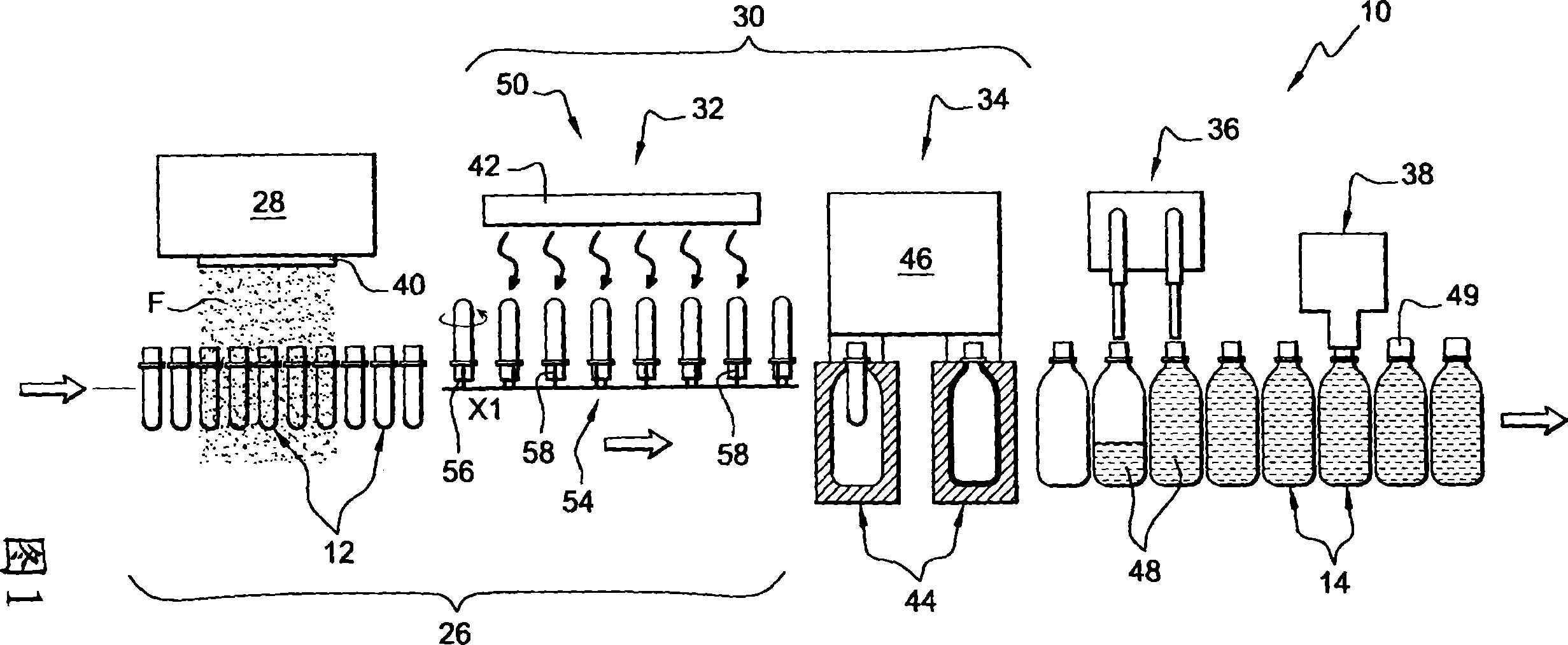
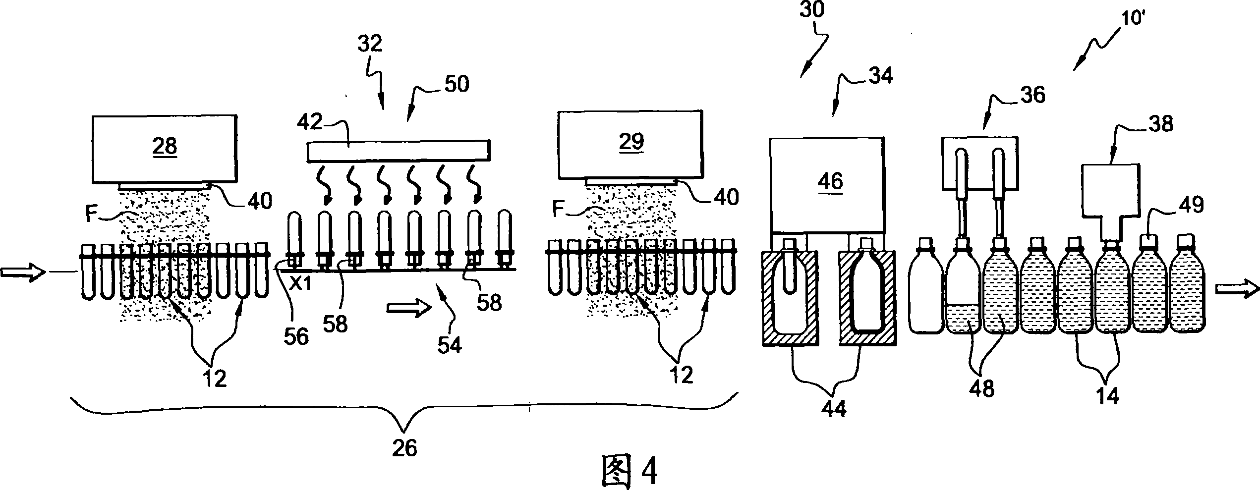
[0049] [49] FIG. 1 shows a plant 10 for the production of bottles 14, in particular aseptic or sterile bottles, advantageously obtained from plastic preforms 12 by blow molding.

[0050][50] Such a plant 10 is used, for example, for the manufacture of plastic bottles 14, such as polyethylene terephthalate (PET).

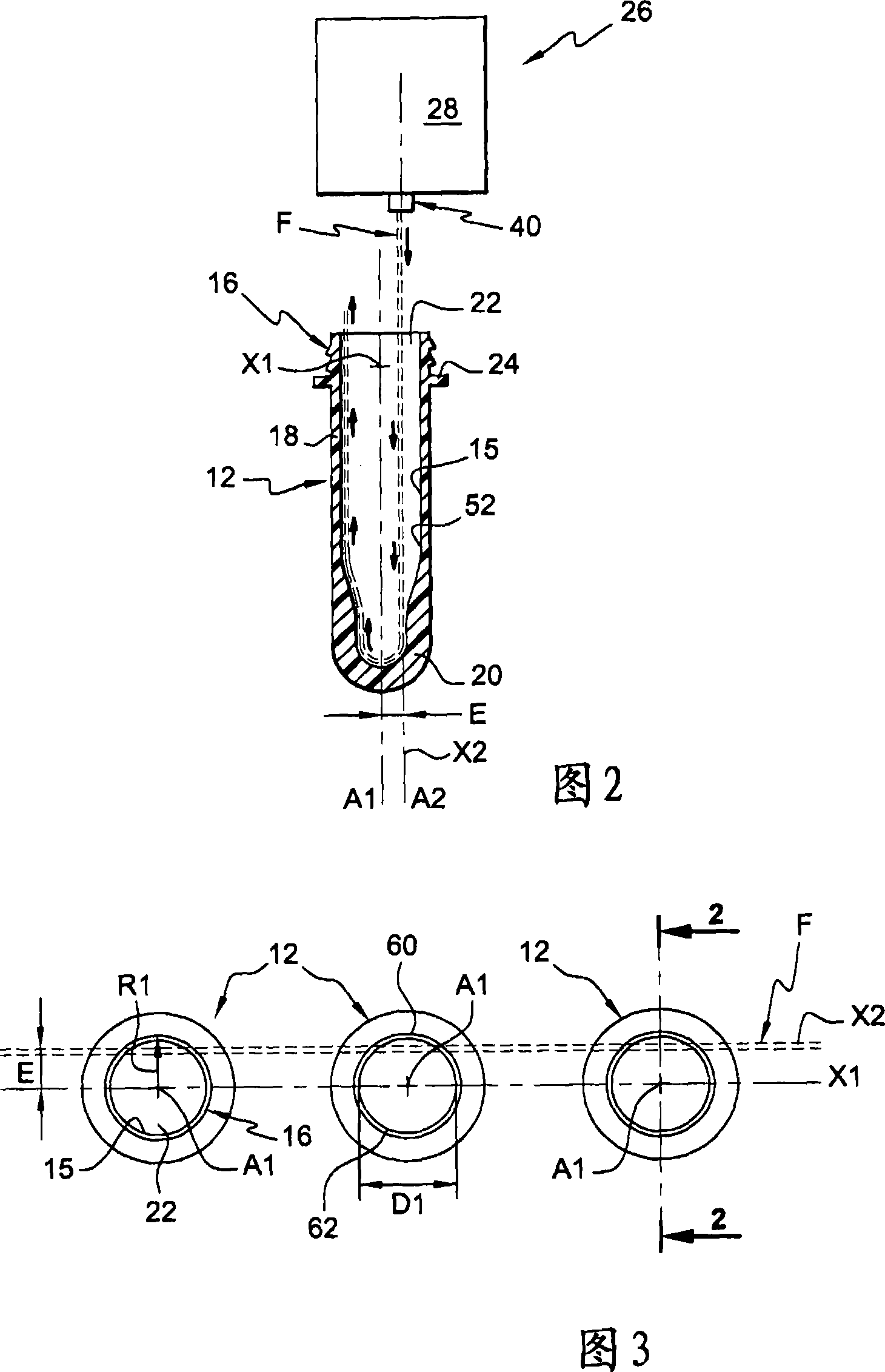
[0051] [51] Each preform 12 generally has the shape of a tube closed at one end and already having the final shape of the neck 16 of the bottle 14 at the other end.

[0052] [52] As a non-limiting example, FIG. 2 shows a preform 12 whose cylindrical body 18 has an axis A1 extending perpendicularly and coincides with the axis of the neck 16 .

[0053] [53] The lower end 20 of the preform 12 is closed, whereas its upper end forms a neck 16 which delimits an inner opening 22 and is provided here with an outer radial flange 24 .

[0054] [54] The preform 12 is typic...


PUM


Abstract

A sterilization method and an installation for producing sterile bottles by blow molding sterilized preforms includes, at the spraying station, the flow of sterilizing product atomized onto each preform whose temperature (T1) is less than the condensing temperature (Tc) of the sterilizing product so that a film of mist of the sterilizing product deposits by condensation at least onto the inner wall to be sterilized, and, at the activation station of the sterilizing product of the sterilizing unit, each preform treated in the aforementioned manner is heated by radiation to a temperature (T2) greater than or equal to the activation temperature (Ta) in order to sterilize at least the inner wall of the preform.

Description

technical field [0001] [01] The present invention relates to a method of sterilizing preforms and an apparatus for producing sterile bottles from preforms sterilized by this method. [0002] [02] The invention relates in particular to a method of sterilizing plastic preforms for molding, especially blowing, in aseptic bottle production plants. [0003] [03] The invention also relates to an apparatus for producing sterile bottles from plastic preforms using the preform sterilization method according to the invention, in which apparatus the preforms are conveyed in a continuous flow flowing from upstream to downstream to In equipment, said equipment has at least successively: [0004] [04] - Sterilization unit having at least one injection station equipped with at least one nozzle in order to spray a stream of sterilizer in the form of a steam jet towards the neck of each preform to be sterilized during the treatment ; [0005] [05] - Forming unit with a thermal conditioning ...

Claims


Application Information

Patent Timeline
IPC IPC(8): B29C49/42B29C49/46
CPCB29C49/46B29C49/42B29B2911/14106B29B2911/1402A61L2202/23B29K2067/00B29C49/4205B29B2911/14133B29B2911/1404B29C49/06B29C2791/005A61L2/208B29B2911/14033B67C2003/227B29B2911/14026B29C2949/26B29C2949/28B29C2949/24B29C2949/22B29C2949/3024B29C2949/3032B29C49/42405B29C2949/0715B29C2049/7831B29C2049/7862
Inventor E·阿德里安森斯S·埃贝尔
Owner SIDEL PARTICIPATIONS SAS
Learn More