Coated cemented carbide endmill

A cutting tool and coating technology, applied in the direction of coating, tools for lathes, metal material coating process, etc., can solve problems such as chipping and breaking of cutting edges

Inactive Publication Date: 2008-06-25
SANDVIK INTELLECTUAL PROPERTY AB
View PDF3 Cites 21 Cited by
  • Summary
  • Abstract
  • Description
  • Claims
  • Application Information

AI Technical Summary

Problems solved by technology

This cutting edge often suffers from chipping problems or breaks

Method used


Image

  • Coated cemented carbide endmill

Examples


example 1

[0056]Uncoated cutting tools, WC-10% Co inserts for turning ISO type CNMG120408 were cleaned and subjected to a PVD coating process according to the following. The blades were loaded into a reactive arc evaporation type PVD apparatus chamber containing six metal evaporation sources arranged in pairs. The blade further undergoes a triple rotation to coat it evenly. One pair of evaporators had Ti metal targets and the other two had AlTi alloy targets with a compositional atomic ratio Al / Ti of 2. The chamber is evacuated, followed by heating and plasma etching steps to further clean the knives and condition the blade surface by removing excess binder from the blade surface. TiN and (Ti,Al)N alloy layers were deposited at a temperature of 600°C by metal evaporation while maintaining a partial pressure of nitrogen in the coater, and using appropriate selection of active evaporation sources and ratios. Process conditions in the deposition step are as follows:

[0057] Table 1

...

example 2

[0067] Inserts from Example 1 were subjected to a coating process using the parameters according to Table 3 to deposit an additional interlayer of the second type.

[0068] table 3

[0069] Floor

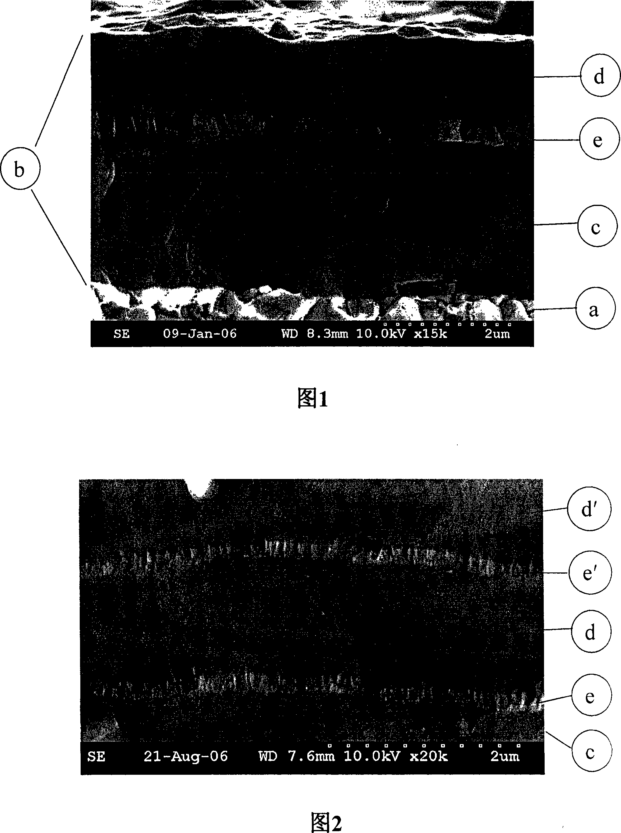
[0070] The fractured cross-section of the coating is shown in the SEM micrograph in FIG. 2 .

[0071] Inserts were analyzed using the same technique as in Example 1. The results are shown in Table 4.

[0072] Table 4

[0073] Floor

[0074] * Estimates made on measurements of a single layer coating deposited under the same conditions and having a composition and thickness consistent with that of the layer. After deposition of layers e and d, it is desired that the residual stress of layer c remain at substantially the same stress level.

example 3

[0076] The coating according to example 1 was deposited to a thickness of 4.2 μm on a solid carbide ball nose end mill with a diameter of 10 mm. A similar end mill with the same cemented carbide composition was coated with a prior art (Ti,Al)N single layer coating with an Al / Ti atomic ratio of 2.0 and a thickness of 2.9 μm . The two end mill variants were evaluated in a dry milling test for profile milling of 1.2379 steel with a hardness of HRC58. The cutting speed is 170m / min, the feed speed is 0.12mm / tooth, and the cutting amount is a p =a e = 0.2 mm. The tool life (expressed in milling distance m) up to the maximum wear amount of 0.40 mm is shown in Table 5. The results show that the coatings of the invention have superior performance in demanding milling operations on superhard steels.

[0077] table 5

[0078] Coated solid carbide end mill test


PUM

PropertyMeasurementUnit
thicknessaaaaaaaaaa
thicknessaaaaaaaaaa
particle sizeaaaaaaaaaa

Abstract

The present invention relates to a cemented carbide endmilling tool for semifinishing and finishing machining of hardened steels of HRC above 46, comprising a substrate and a wear resistant coating comprising a substrate and a wear resistant coating. The substrate, a, comprises 90-94 wt% WC in a binder phase of Co also containing Cr in such an amount that the Cr/Co weight ratio is 0.05-0.18. The wear resistant coating, b, is 1.8-9.5 µm thick, and comprises a first layer, c, of a hard and wear resistant refractory PVD AlMe nitride or carbonitride where Me is Zr, V, Nb, Cr or Ti having a thickness of 1.0-4.5 µm and an atomic fraction of Al to Me of 1.20-1.50, a second layer, d, of hard and wear resistant refractory PVD AlMe nitride or carbonitride where Me is Zr, V, Nb, Cr or Ti, having a thickness of 0.5-4.5 µm, and an atomic fraction of Al to Me of 1.30-1.70, and in between the first layer (c) and the second layer (d), a 0.05-1.0 µm thick low-A1 layer, (e), the thickness being less than 0.95 times the thickness of thinnest of the first layer (c) and the second layer (d), of an AlMe nitride or carbonitride where Me is Zr, V, Nb, Cr or Ti and an atomic fraction of Al to Me of 0-0.3.

Description

technical field [0001] The invention relates to a coated cutting tool for metalworking, such as an insert in a tool holder system for turning, milling or drilling, or a solid tool such as a drill or an end mill, the coated cutting tool having Tungsten carbide or cermet body and refractory coating, so that the tool has good wear resistance, toughness and cutting edge chipping resistance. Background technique [0002] In the metal cutting industry there is a constant quest to increase productivity and demand higher cutting speeds and feeds with extended tool life. In order to meet these requirements, the development of cutting tool materials mainly focuses on improving the toughness and wear resistance of cutting tools. [0003] By depositing wear-resistant coatings using physical vapor deposition PVD or chemical vapor deposition CVD techniques, the wear resistance can be significantly improved compared to uncoated tools. [0004] Significant improvements to coated cutting t...

Claims


Application Information

Patent Timeline
Patent Type & Authority Applications(China)
IPC IPC(8): B32B33/00B32B9/00C23C14/06C23C14/24
CPCC22C29/08C23C28/044C23C14/0641C23C30/005C23C28/00B23B27/148C23C14/0664C23C14/325
Inventor 托尔比约恩·塞林德马茨·阿尔格伦
Owner SANDVIK INTELLECTUAL PROPERTY AB
Why Eureka
Try Eureka