

Metallurgical slag treatment method and treatment apparatus
A processing method and technology of a processing device, which are applied in the direction of recycling technology, etc., can solve the problems of inability to granulate slag at low temperature, and achieve the effects of favorable environmental protection, easy control and cost saving.
- Summary
- Abstract
- Description
- Claims
- Application Information
AI Technical Summary
Problems solved by technology
Method used
Image

Examples
Embodiment 1
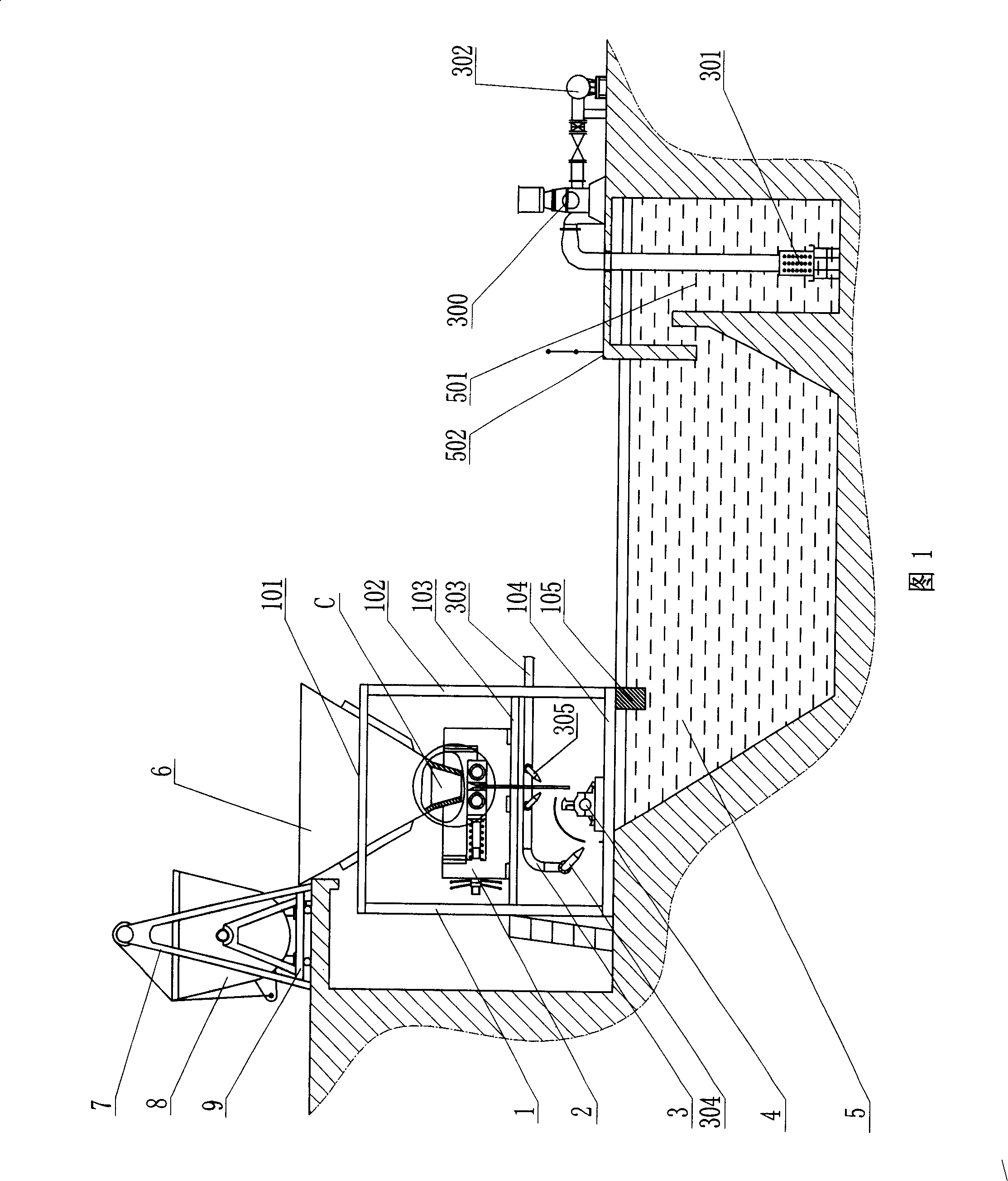
[0029] Referring to Fig. 1 and Fig. 11, a kind of metallurgical slag processing method, its processing step is:
[0030] The metallurgical slag in the smelting furnace is collected in a slag tank, and the slag tank is transported to a tilting device through the conveying equipment; the metallurgical slag is a thick slag, and the slag tank 8 is a conventional equipment, the conveying equipment is a conventional slag truck 9, and the tipping device is a conventional tipping machine 7;
[0031] Start the tilting device to tip the metallurgical slag into a slag rolling device. There is a hopper above the slag rolling device. A pair of rotating rolls are installed at the bottom outlet of the hopper, and the metallurgical slag is fed through the hopper. Rotating rolls that roll the metallurgical slag into flaked slag 600 (see Figure 6 ), and continuously output to the outside; the slag rolling device is a roller rolling machine 2, and the hopper is a slag receiving hopper 6 made o...
Embodiment 2
[0040] see Figure 10 , a metallurgical slag processing method, the steps of its processing are:
[0041] Collect the metallurgical slag in the smelting furnace into a slag tank, and transport the slag tank to a tilting device by means of conveying equipment;
[0042] Start the tipping device to tip the metallurgical slag into a slag rolling device, and the roll rolls the metallurgical slag into a flake-shaped slag, and continuously outputs it to the outside;
[0043] In this embodiment, the thickness of the flaky slag is 0.5-100 mm, preferably kept at 5 mm. The smaller the thickness of the flaky slag, the faster its temperature drops.
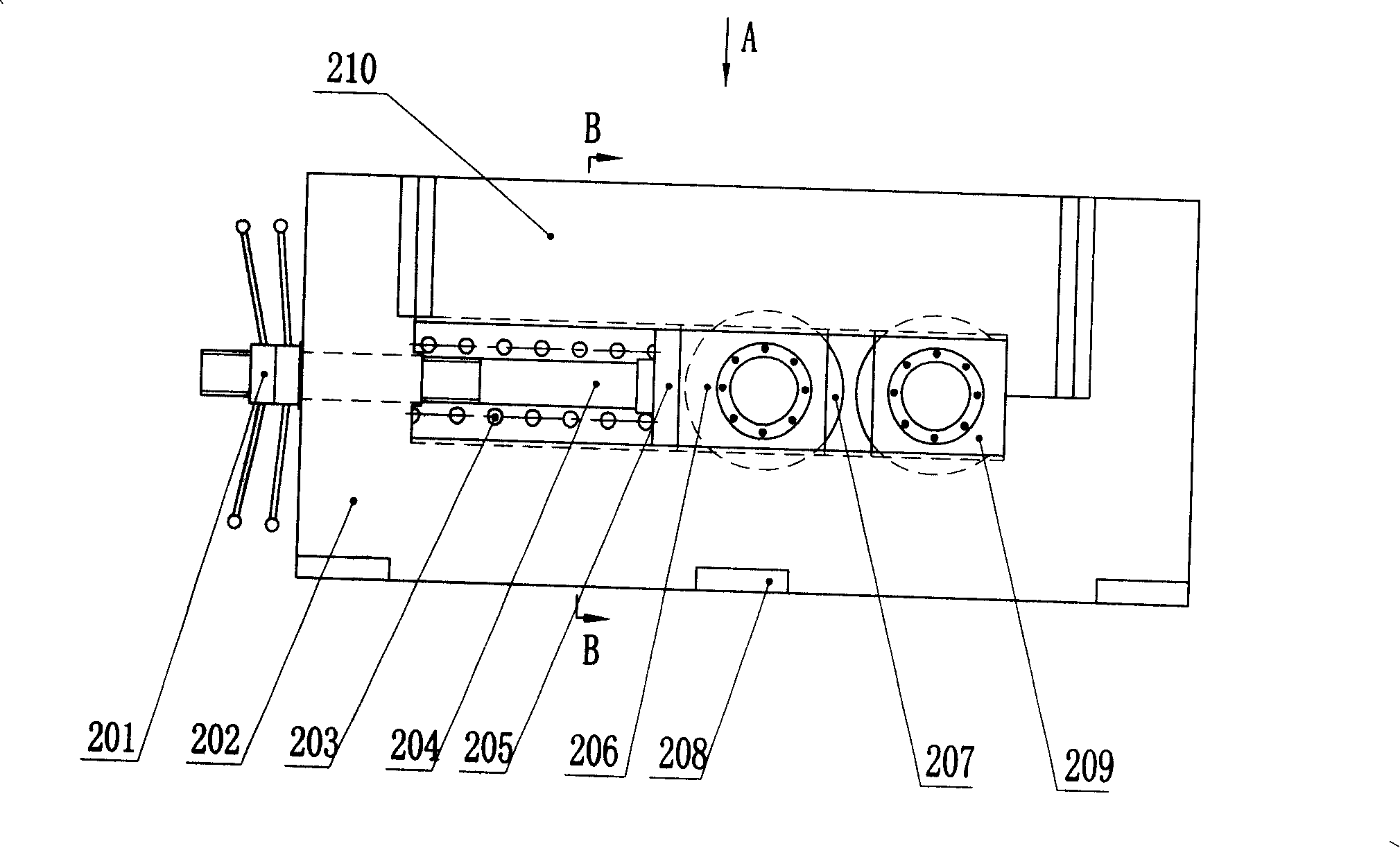
[0044] For the equipment used in this example see Figure 10 , image 3 , Figure 4 ,Figure 5, Figure 6 , (Figure 5 shows the structure of the lower stand, and the upper stand is removed) The slag rolling device includes two rotating rolls 207, a drive motor 213 for driving the rolls to rotate, a gear reducer 212, with a universal The dri...
Embodiment 3
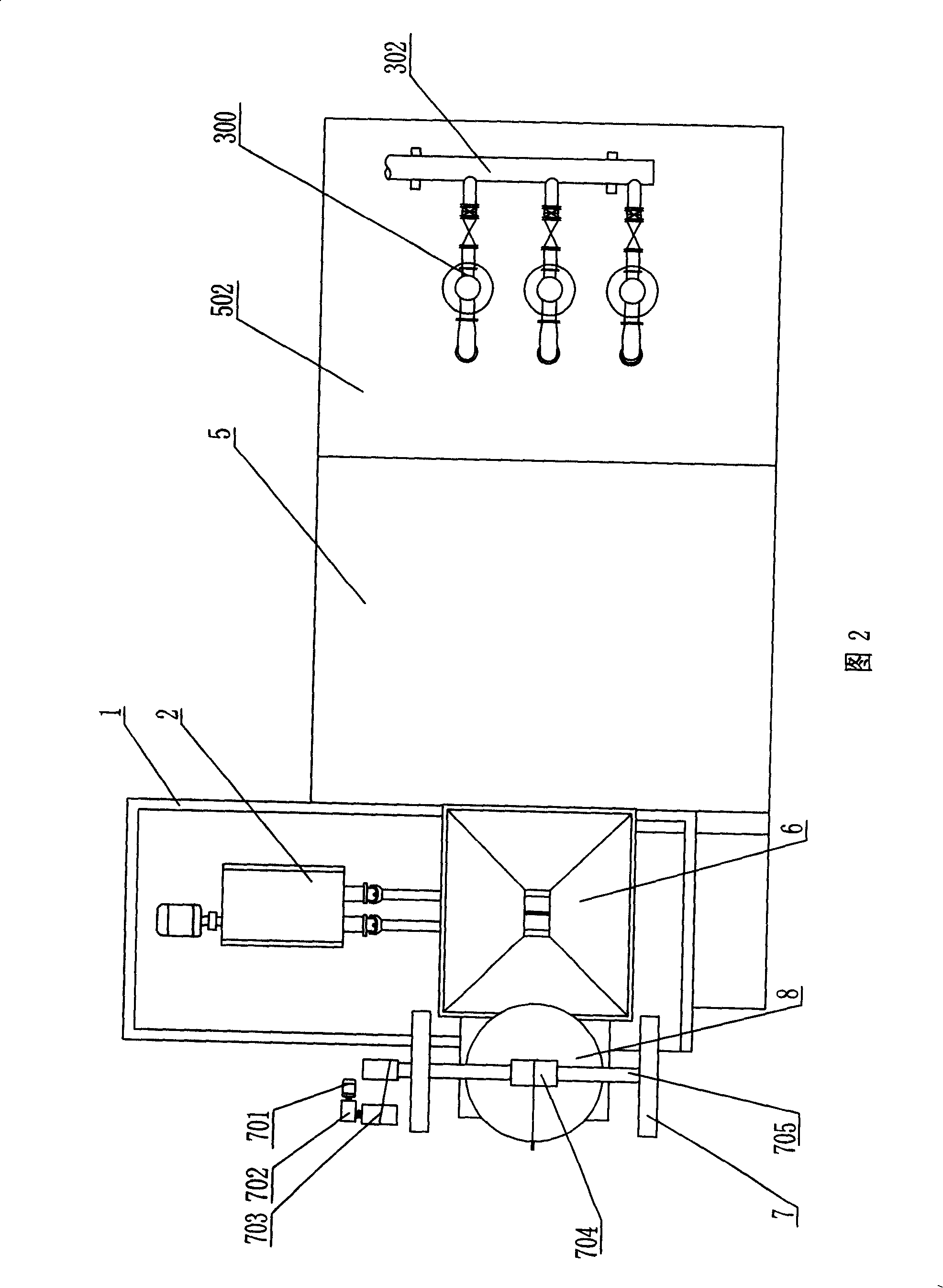
[0046] A metallurgical slag processing device, referring to Fig. 1 and Fig. 2, comprises a mounting frame, a slag rolling device, a water spray cooling device, and a crushing device; the mounting frame is a frame 1 of a steel structure, and its upper part A hopper 6 is set, the slag rolling device 2 is set at the outlet at the bottom of the hopper, the water spray cooling device 3 is set at the bottom of the installation frame, the crushing device 4 is set at the bottom of the installation frame, and the crushing device The crushing operation end of the slag rolling device corresponds to the output end of the slag rolling device; in the figure, the right side of the crushing device is the crushing operation end, and the bottom of the slag rolling device is the output end; a cooling water pool is set under the installation frame 5.
[0047] In this embodiment, the installation frame is a frame made of steel, which is composed of a plurality of columns 102 and a plurality of hor...
PUM
 Abstract
Description
Claims
Application Information