High speed and high precision micro stamping drive system based on dual linear motors

A drive system, linear motor technology, applied in circuits, electrical components, microstructure technology and other directions, can solve the problem of inability to meet the microplastic forming of parts, and achieve accurate and controllable speed-displacement, high positioning accuracy, and improved service life. Effect

Active Publication Date: 2011-12-28
HARBIN INST OF TECH
View PDF0 Cites 2 Cited by
  • Summary
  • Abstract
  • Description
  • Claims
  • Application Information

AI Technical Summary

Problems solved by technology

[0003] The purpose of this invention is to provide a high-speed and high-precision micro-stamping drive system based on dual linear...

Method used


Image

  • High speed and high precision micro stamping drive system based on dual linear motors
  • High speed and high precision micro stamping drive system based on dual linear motors
  • High speed and high precision micro stamping drive system based on dual linear motors

Examples


specific Embodiment approach 1

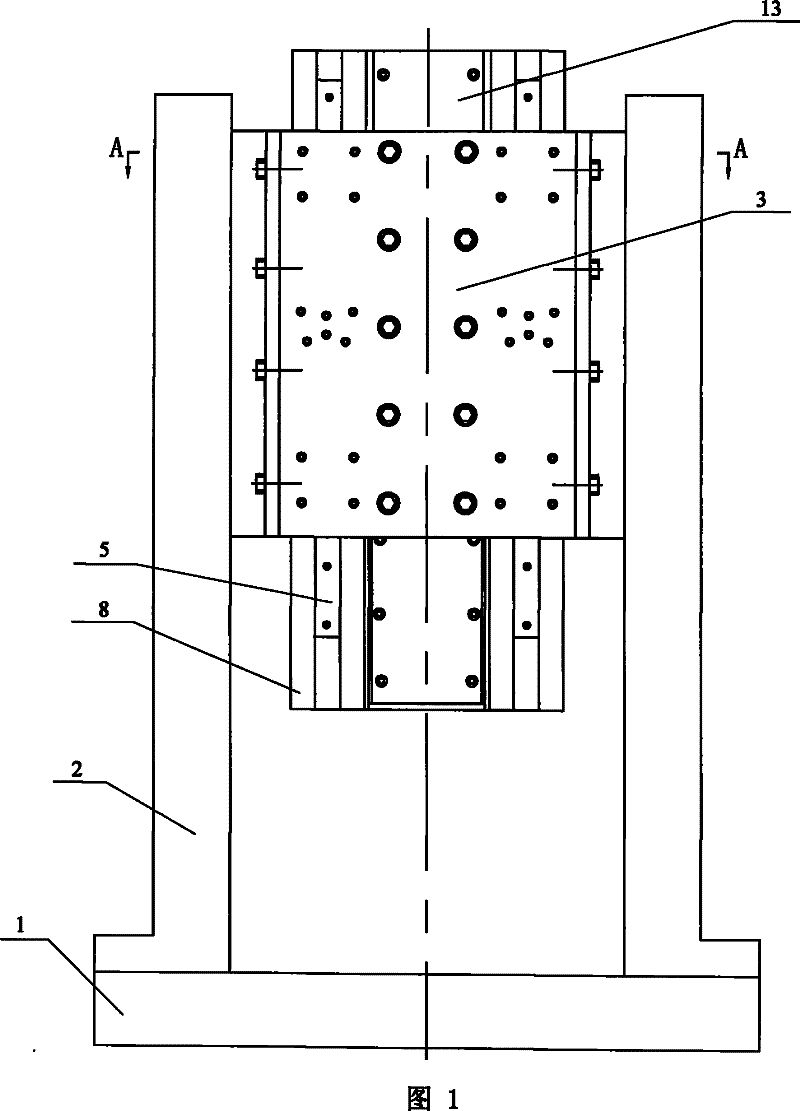
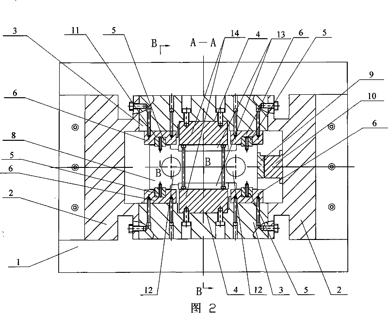
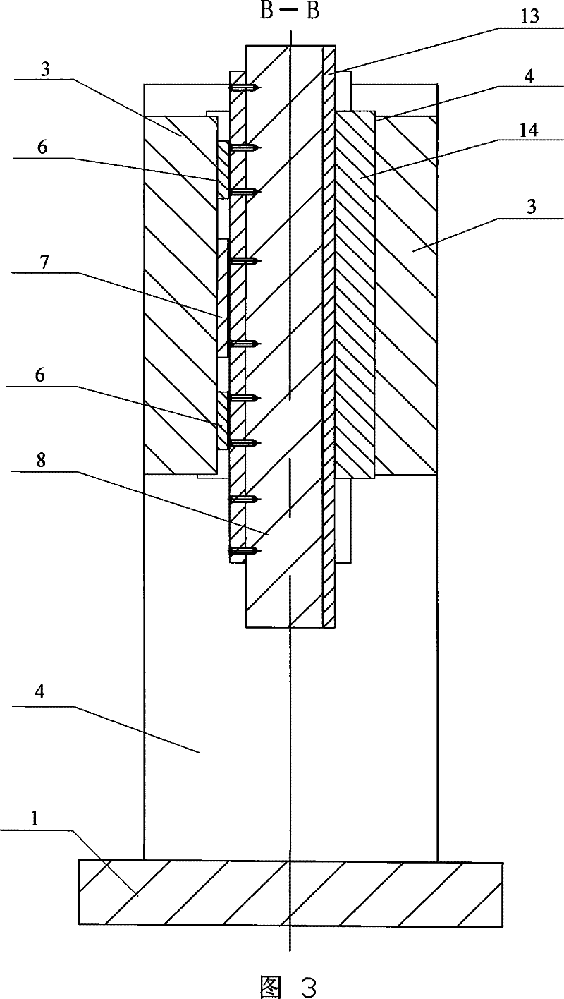
[0007] Specific implementation mode one: combine Figure 1 ~ Figure 3 Describe this embodiment, this embodiment consists of base 1, two racks 2, two brackets 3, two linear motors 4, four guide rails 5, eight guide rail sliders 6, four brakes 7 and sliders 8, grating ruler 9 and grating ruler probe 10; the lower ends of the two frames 2 are fixedly connected to the left end and the right end of the upper end surface of the base 1 respectively, and the two brackets 3 are arranged side by side between the two frames 2 front and rear and respectively connected to the The two racks 2 are fixedly connected, and the two brackets 3 are used as supports for the two linear motors 4; the slider 8 is installed between the two brackets 3, and a linear motor is arranged symmetrically at the front end and the rear end of the slider 8 4. It can obtain good acceleration performance and large output load, and can ensure that the center of the output force is consistent with the center of the eq...

specific Embodiment approach 2

[0009] Specific implementation mode two: combination figure 2 To illustrate this embodiment, two longitudinal weight-reducing through holes 12 are provided on the upper end surface of the slider 8 of this embodiment at positions symmetrical to the central axis. With this setting, good acceleration performance can be obtained. Under the same force, the lighter the moving part, the better. Other components and connections are the same as those in the first embodiment.

[0010] The working process of the system of the present invention is: in order to ensure the synchronization of the motion of the two linear motors, the two linear motors are controlled by a set of controllers. According to the specific forming process, the motion trajectory of the linear motor is formulated, that is, the output displacement-time curve of the linear motor, and the linear motor controller controls the motion of the linear motor according to the motion trajectory. At the beginning of the movemen...


PUM


Abstract

The invention relates to a high-speed and high-precision micro-punching drive system based on double linear motors, which relates to a high-speed and high-precision micro-punching forming drive device for micro parts. The invention can solve the problem that the driving device of the traditional forming equipment cannot satisfy the microplastic forming of parts. The two frames (2) are fixedly connected to the left and right ends of the base (1), the two brackets (3) are fixedly connected to the two frames (2), and the slider (8) is installed between the two brackets (3). Between, the front and rear ends of the slider (8) are symmetrically provided with a linear motor (4), the primary (14) of the linear motor (4) is fixedly connected with the support (3), and the secondary (13) of the linear motor (4) Fixedly connected with the slide block (8), four guide rails (5) are fixedly installed on the slide block (8), and the guide rail (5) slides and cooperates with the guide rail chute (11) of the guide rail slider (6), and the guide rail slide block (6 ) is fixedly connected with the bracket (3), the air brake (7) fixedly connected with the bracket (3) is arranged directly above the four guide rails (5), the grating scale (9) is fixedly mounted on the slide block (8), and the grating scale The probe (10) is set close to the grating ruler (9) and fixed on the frame (2). The invention can realize low-cost, large-volume microplastic parts forming.

Description

technical field [0001] The invention relates to a driving device for high-speed and high-precision micro-stamping forming of micro parts. Background technique [0002] The geometric size of the parts in microplastic forming is very small, which puts forward high requirements on the movement speed, positioning accuracy and forming efficiency of the forming equipment, and requires the equipment to be able to achieve precise control of displacement and forming force. The driving device of traditional forming equipment can no longer meet the needs of microplastic forming. For example, the crank drive equipment cannot automatically control the pressure due to its fixed displacement-time characteristic; although the hydraulic and pneumatic drive equipment can meet these requirements, they cannot achieve fast stamping frequency; although the piezoelectric drive forming system has a fast response speed, The output force and working stroke can also be adjusted, but the output displa...

Claims


Application Information

Patent Timeline
IPC IPC(8): G05D3/12B81C5/00B81C99/00
Inventor 单德彬曲东升王春举陈立果徐杰李娟荣伟彬郭斌孙立宁
Owner HARBIN INST OF TECH
Why Eureka
Try Eureka