
Method for inhibiting voltage transformer noise caused by DC magnetic biasing

A DC bias, transformer technology, applied in the direction of transformer/inductor noise damping, electrical component structure association, electrical components, etc., can solve the problems of reduced reliability of thyristors, difficult to achieve ideal conditions, complex practical applications, etc. Manufacturing/usage cost and maintenance effort, avoidance of control loops and thyristor components, effect of downsizing

Active Publication Date: 2008-06-25
SHANGHAI MUNICIPAL ELECTRIC POWER CO +1
View PDF0 Cites 7 Cited by
  • Summary
  • Abstract
  • Description
  • Claims
  • Application Information

AI Technical Summary

Problems solved by technology

[0015] The above methods have their own advantages and disadvantages. The first method is simple and feasible, but it is not thorough. The effect is related to the ground potential difference. If the ground potential difference is large and the grounding resistance is restricted by the system and it is not appropriate to increase it, the effect will be poor.
The second method is a more thorough suppression method, but due to the use of control and protection circuits such as the triggering of thyristors, the reliability has decreased, and some uncertain factors
The third method is theoretically feasible, but the actual application is more complicated and difficult to achieve the ideal situation, and the injected DC current brings other problems

Method used


Image

  • Method for inhibiting voltage transformer noise caused by DC magnetic biasing

Examples


Embodiment Construction

[0033] The present invention will be further described below in conjunction with the accompanying drawings.

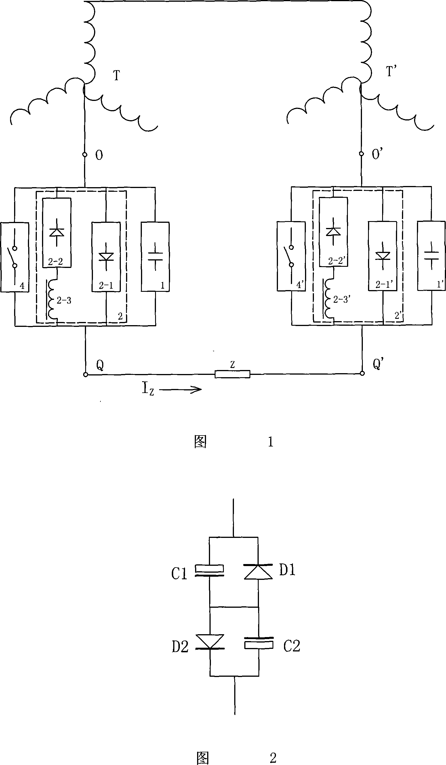
[0034] In Fig. 1, the present invention includes setting parallel DC blocking unit 1 (or 1') and primary system fault protection unit 2 (or 2'), its invention and creation point is that two polarized electrolytic capacitors are connected in series in reverse polarity, and a diode is parallel connected in reverse polarity at both ends of each electrolytic capacitor (see Figure 2 for the specific connection method ), while protecting the capacitance, eliminate the half-capacity effect caused by the series connection of equal capacitance, and use the nonlinear resistance characteristics of the diode to form a complete DC blocking unit 1 (or 1′) with a good AC channel.

[0035] In other words, its DC blocking unit includes a first electrolytic capacitor, a second electrolytic capacitor, a first protection diode and a second protection diode, and the first and second electr...


PUM


Abstract

The invention relates to a method of restricting the direct current magnetic bias to generate the noise of the transformer, which belongs to the emergency protection circuit device field. The invention comprises a stopping direct unit and a primary system fault protection unit, the invention is characterized in that two electrolytic capacitances with polarities are connected in series in an inverted polarity way, and a diode is in parallel connected at the both ends of each electrolytic capacitance in a reverted polarity way, so as to form a stopping direct unit; at least more than two diodes are connected in series in sequence in an identical direction way, so as to form an unidirectional overvoltage protection circuit, and two unidirectional overvoltage protection circuits are connected in parallel in a reverse direction way, so as to form a complete primary system fault protective unit. The continuity of the grounding circuit is guaranteed during the changing process of the grounding current at the whole central point from small to large, the complex controlling circuit and the thyristor element are avoided, no risk of the stopping direct component is guaranteed by a built-in auto bypass, the structure parameter of the prior electric network is not changed, and simultaneously, the direct current component can be completely partitioned during the normal operation.

Description

technical field [0001] The invention belongs to the field of emergency protection circuit devices, and in particular relates to an emergency protection circuit device for suppressing a DC current at a neutral point of a transformer. Background technique [0002] With the construction of my country's power grid, more and more direct current transmission lines (also known as high-voltage direct current transmission) have been put into operation, which has played a very active role in the interconnection of regional power systems. [0003] When the DC transmission system operates on a single pole (also known as asymmetric operation), a DC voltage difference will be generated on the ground surface. The same result may also be caused by DC grounding in industrial production (such as DC electrolysis, etc.). [0004] Due to the DC potential difference of the earth, when the transformers at both ends of the transmission line adopt the neutral point grounding method, the DC different...

Claims


Application Information

Patent Timeline
Patent Type & Authority Applications(China)
IPC IPC(8): H02H7/04H01F27/33H01F27/40
Inventor 戴春怡
Owner SHANGHAI MUNICIPAL ELECTRIC POWER CO
Learn More