
Turbo rocket with real Carnot cycle

A rocket engine and engine technology, applied in rocket engine devices, combined engines, engine components, etc., can solve problems such as non-implementation

Inactive Publication Date: 2008-06-25
马里厄斯・A・保罗
View PDF1 Cites 6 Cited by
  • Summary
  • Abstract
  • Description
  • Claims
  • Application Information

AI Technical Summary

Problems solved by technology

However, so far the true Carnot cycle has not been implemented in a physical embodiment that effectively follows the cycle's four phases

Method used


Image

  • Turbo rocket with real Carnot cycle
  • Turbo rocket with real Carnot cycle
  • Turbo rocket with real Carnot cycle

Examples


Embodiment Construction

[0039] Detailed description of the preferred embodiment

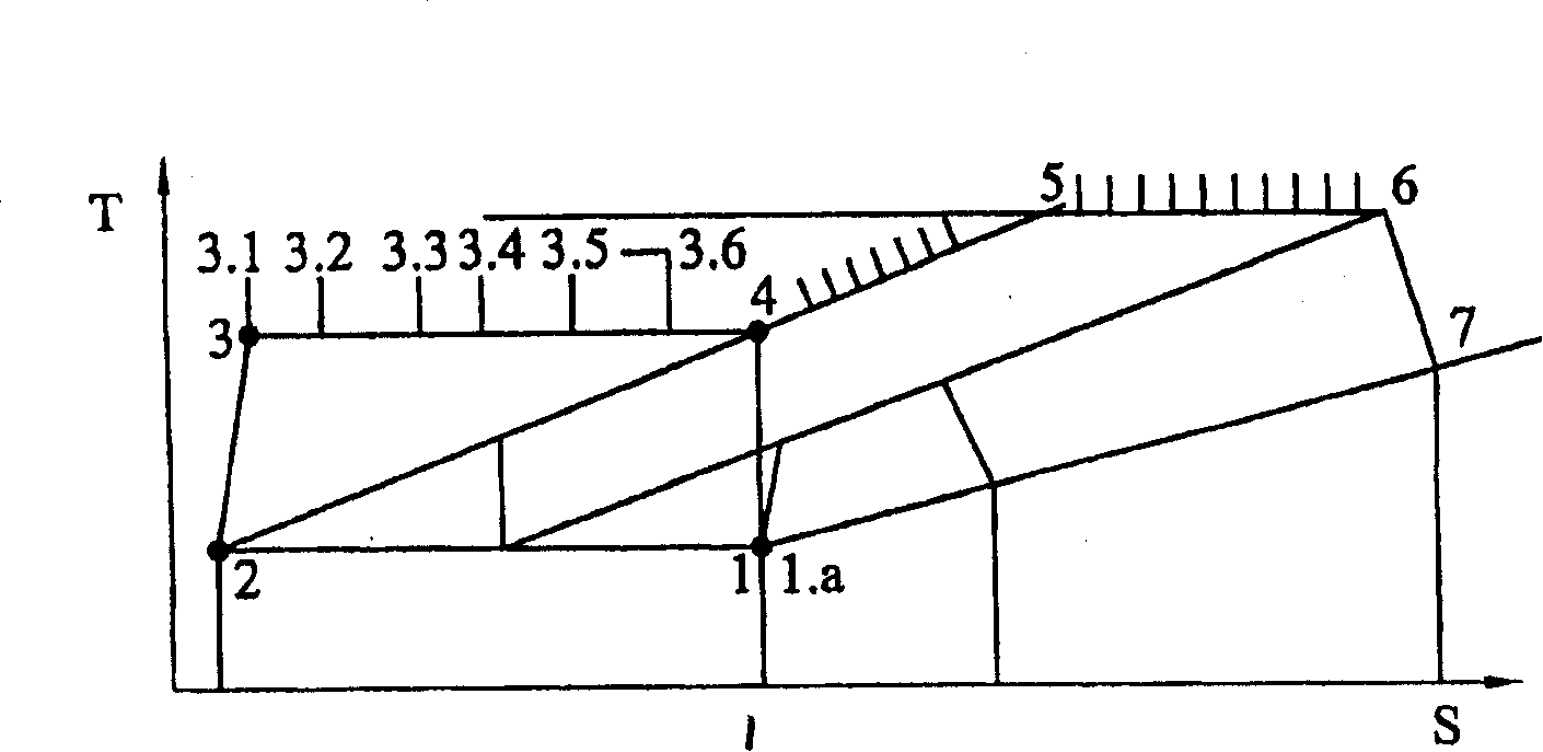
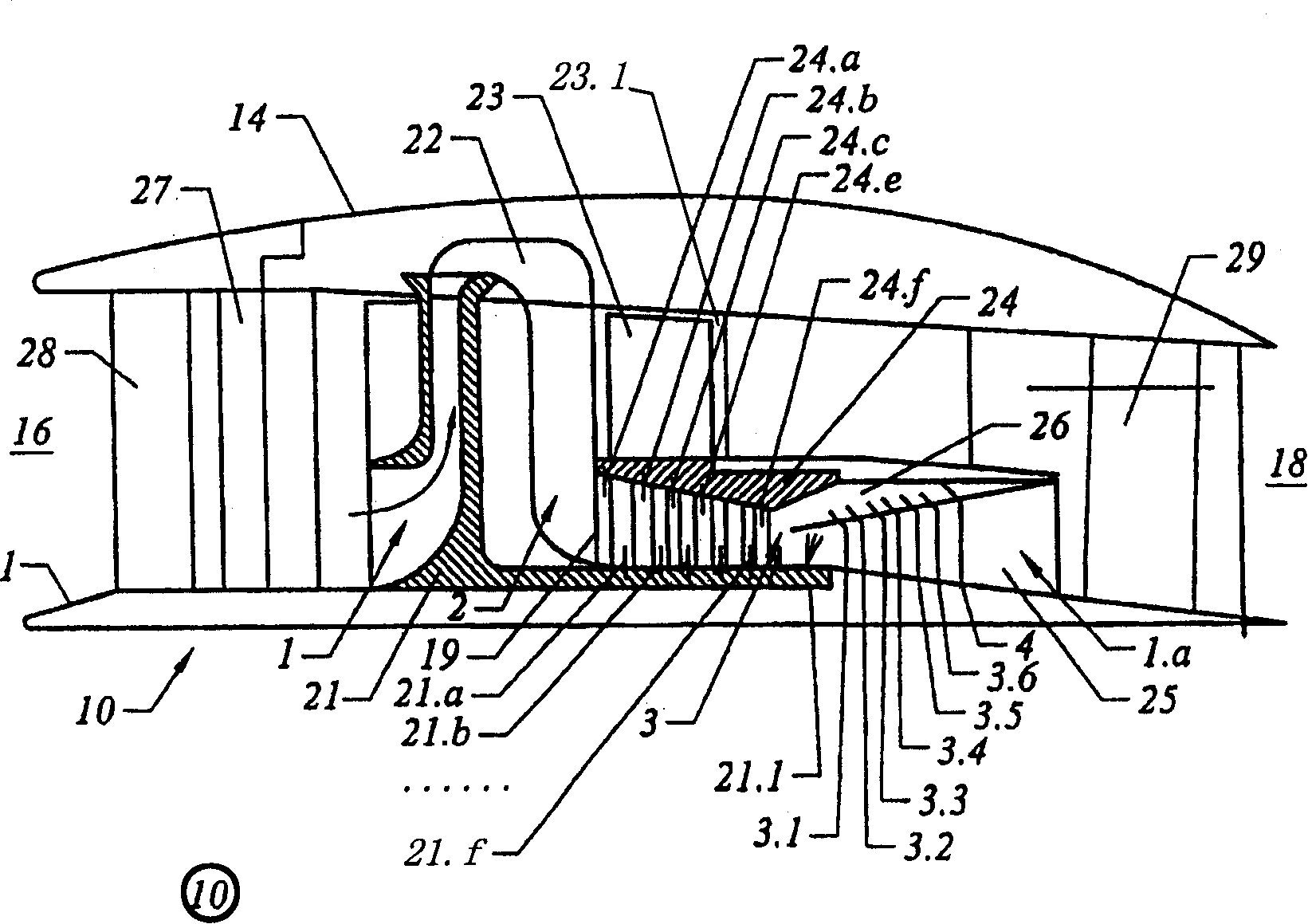
[0040] refer to figure 1 and 2 ,exist figure 2 The turbo rocket engine shown schematically in and generally identified by the reference numeral 10 follows figure 1 The real Carnot cycle shown in . exist figure 1 In the T-S diagram of , the first embodiment 20 of the turbo rocket engine 10 goes through: isothermal compression from points 1 to 2, polytropic (adiabatic) compression from points 2 to 3, and from points 3.1 to 3.2 to 3.3 to 3.4 to Staged asymptotic isotherms from 3.5 to 3.6 to 4 burn and expand stoichiometrically. With a final polytropic (adiabatic) expansion to 1.a, the cycle is essentially complete.

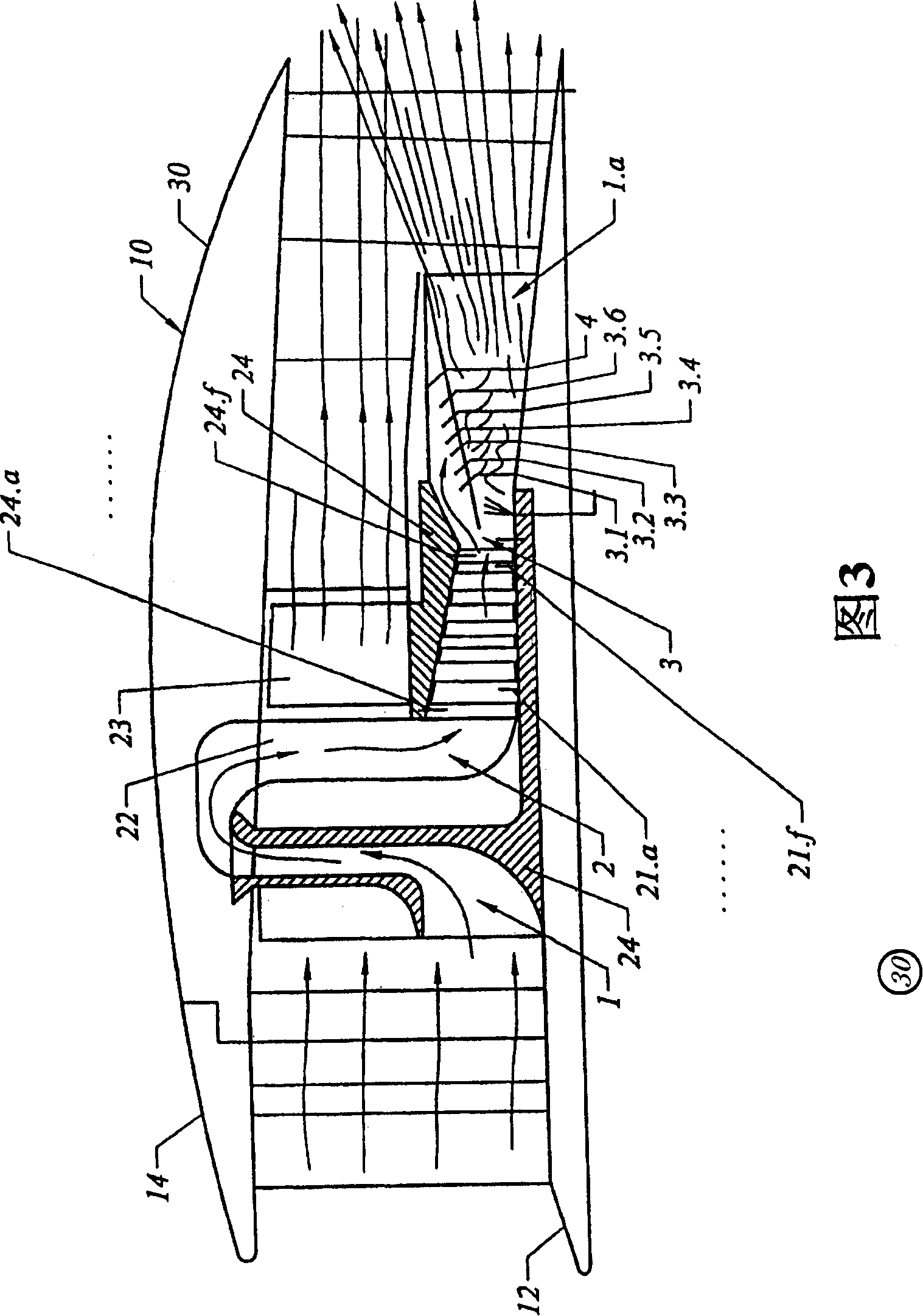
[0041] Within the turbo rocket engine 10 in these figures, there is generally a central core 12 and an outer casing 14 having an inlet opening 16 and an air outlet 18, and a combination of passages from the inlet opening 16 to the air outlet 18 that create a unique cycle of operation .

[0042] exist ...


PUM


Abstract

Engine embodiments primarily designed for aircraft propulsion and power generation incorporating the Carnot cycle for efficient combustion with typical embodiments including air compressors having one or more stages with isothermal compression and including combustion and expansion chambers having in part isothermal expansion before final adiabatic expansion.

Description

[0001] Citations from earlier applications [0002] This application claims priority to the following provisional application: [0003] U.S. Provisional Application No. 60 / 466,270, entitled "Turbo Rocket Engine With True Carnot Cycle," filed April 28, 2003; [0004] U.S. Provisional Application No. 60 / 470,706, entitled "Turbo Rocket Engine With True Carnot Cycle and Diverging Blades," filed May 15, 2003; [0005] U.S. Provisional Application No. 60 / 486,637, entitled "Turbo Rocket Engine with True Carnot Cycle Continued," filed July 11, 2003, [0006] U.S. Provisional Application No. 60 / 507,400, filed September 30, 2003, entitled "Turbo Rocket Engine with True Carnot Cycle Continuation II." Background of the invention [0007] The present invention relates primarily to combined turbine and rocket engines operating on the Carnot cycle. Also known as a turbo-rocket engine or turbo-rocket engine, the combined turbine and rocket engine is designed to provide a fuel-efficient pro...

Claims


Application Information

Patent Timeline
Patent Type & Authority Applications(China)
IPC IPC(8): F02K5/00F02KF02K3/02
CPCF02C7/143F05D2260/40311F02K1/1207F05D2260/202F02C3/36F02C3/073F02K7/16F02C3/08F02C3/067F02K7/18F02K3/10F02K3/105F02K9/78Y02T50/676F02C7/042F01D5/187
Inventor 马里厄斯·A·保罗
Owner 马里厄斯・A・保罗
Learn More