Method for increasing precision of doppler radar sensor

A Doppler radar and sensor technology, applied in instruments, utilizing re-radiation, reflection/re-radiation of radio waves, etc., can solve the problems of limited accuracy improvement effect, limited bandwidth minimum value, availability limitation, etc., to improve accuracy , the effect of reducing the aperture and the height of the vertical structure

Inactive Publication Date: 2008-06-25
SIEMENS AG
View PDF0 Cites 4 Cited by
  • Summary
  • Abstract
  • Description
  • Claims
  • Application Information

AI Technical Summary

Problems solved by technology

Here, in the case of a conventional elliptical radiation area to the background, the additional effect of limiting the minimum achievable bandwidth occurs
Accuracy gains are limited despite expensive antenna technology
A narrow irradiated background strip in the direction of travel leads, on the one hand, to extremely small correlation lengths within the signal components of the individual scatterers and thus to unreliable measurements, and on the other hand, under high precision requirements Noise stripes hitherto no larger than usual structures in road or track subgrades, such as sleepers or metal casings
Therefore limited usability due to high intensity fluctuations

Method used


Image

  • Method for increasing precision of doppler radar sensor
  • Method for increasing precision of doppler radar sensor
  • Method for increasing precision of doppler radar sensor

Examples


Embodiment Construction

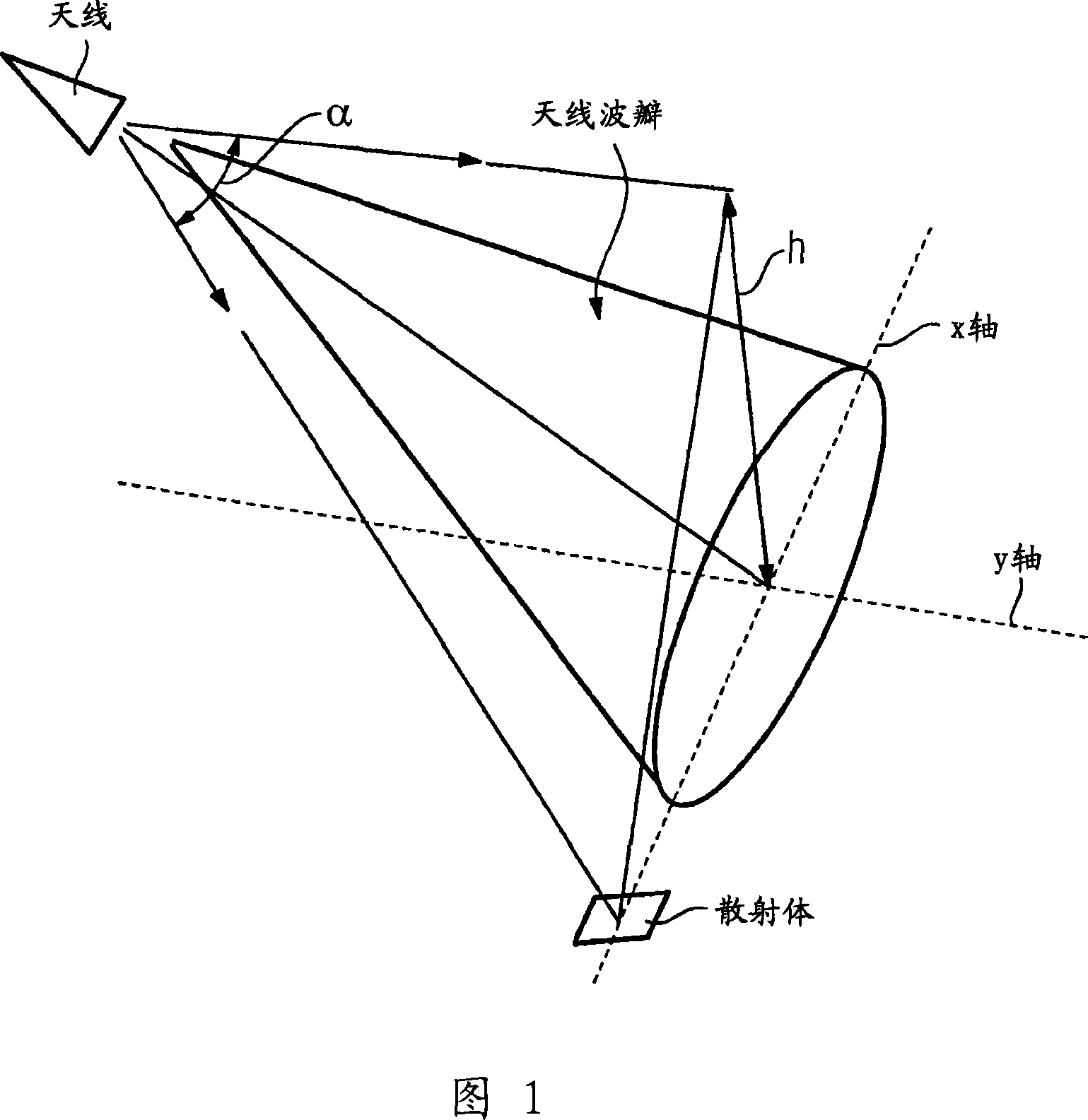
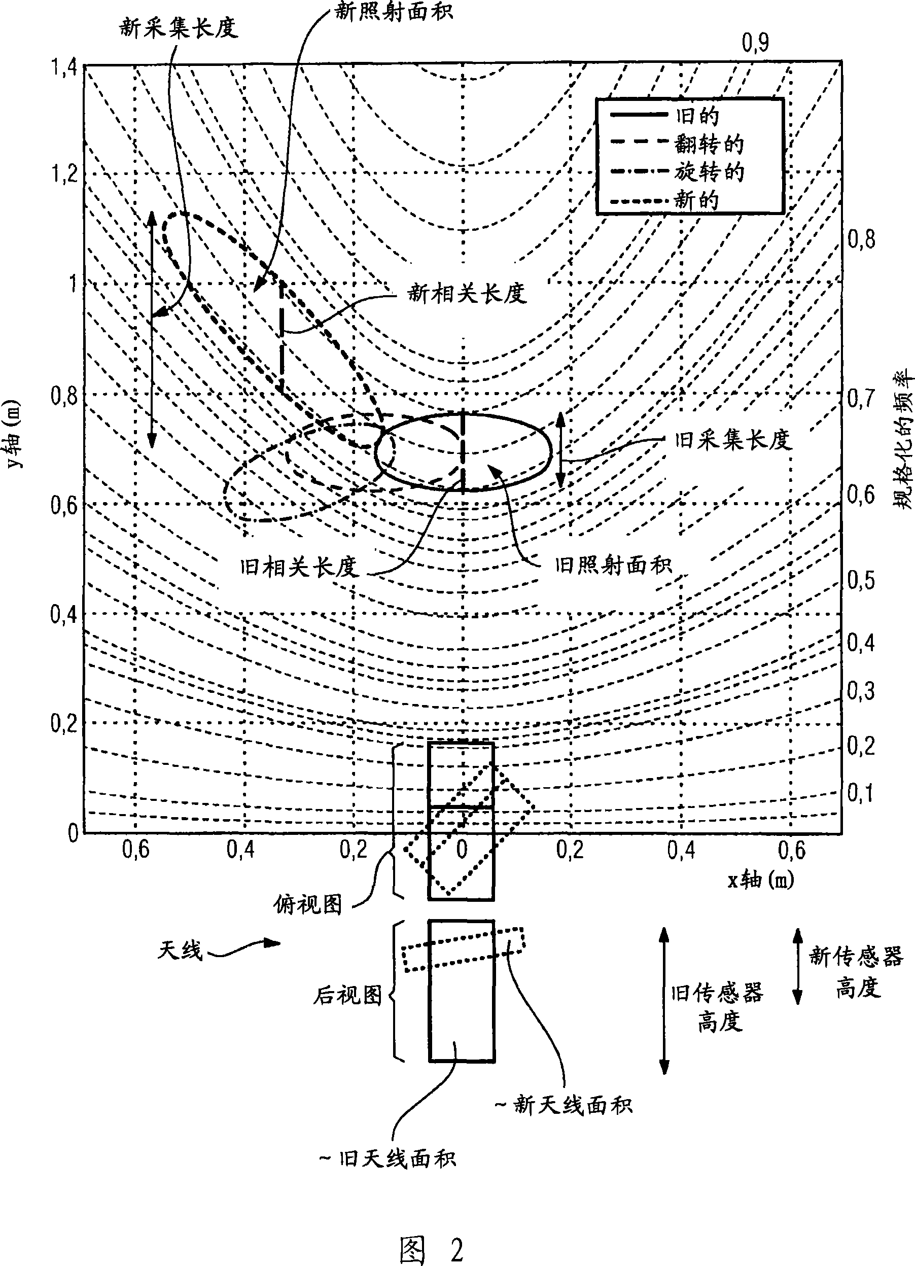
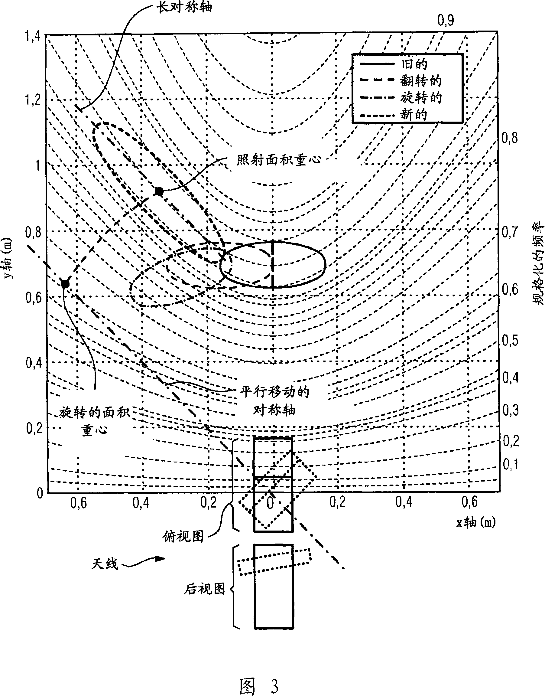
[0017] The following investigation focuses on the model introduction. The starting point here is the lines on the background. Scatterers that contribute the same frequency to the Doppler spectrum are located on these lines. These lines are called iso-Doppler lines. Because only relative characteristics (such as the relative bandwidth of Doppler frequency mixing) are examined here, the Doppler structure is speed-invariant. For a better understanding, let's start with a uniform motion below.

[0018] The Doppler spectrum is formed by the power components weighted in amplitude and frequency of all scatterers illuminated by the antenna. Here, the frequency provided by a single scatterer for the total spectrum depends on the angle between the velocity component in the direction of travel and the velocity component in the direction of the scatterer.

[0019] If a scatterer that causes the same frequency in the spectrum is marked on the background, an iso-Doppler line in the form of a hy...


PUM


Abstract

The invention relates to a method for increasing the precision of a Doppler radar sensor with a microwave transceiver antenna for measuring the vehicle speed on the ground. According to the invention, the microwave transceiver antenna is rotated and / or tipped in such a way that the irradiated underground surface is a long ellipse lying essentially between two precision-limiting iso-Doppler lines.

Description

Technical field [0001] The invention relates to a method for improving the accuracy of a Doppler radar sensor having a microwave transceiver antenna for measuring the speed of a vehicle relative to the ground. Background technique [0002] In the radar speed measurement based on the Doppler effect, the frequency shift of the received microwave relative to the emitted microwave is analyzed. If you emit obliquely to the background, the radiation angle must be considered. Because it is always necessary to radiate a background with a final smaller area, different angular components contribute to the total signal. The analysis of the existing frequency mix contains errors in this way: a large bandwidth also leads to a high measurement error. Therefore, people try to keep the illuminated area as narrow as possible in the direction of movement. For this reason, an expensive antenna with a huge aperture has been required so far. In addition, the pursuit of flat radiation for high-precisi...

Claims


Application Information

Patent Timeline
IPC IPC(8): G01S13/60
CPCG01S13/60
Inventor 亨德里克·伊本多夫克里斯·卡库希克
Owner SIEMENS AG
Why Eureka
Try Eureka