
Dichroic guest-host polarizer

A polarizer, dichroic technology, used in polarizing elements, instruments, nonlinear optics, etc.

Active Publication Date: 2008-06-25
SUMITOMO CHEM CO LTD
View PDF3 Cites 13 Cited by
  • Summary
  • Abstract
  • Description
  • Claims
  • Application Information

AI Technical Summary

Problems solved by technology

However, in mass production of guest-host polarizers, it is not desirable to use a temporary second substrate

Method used


Image

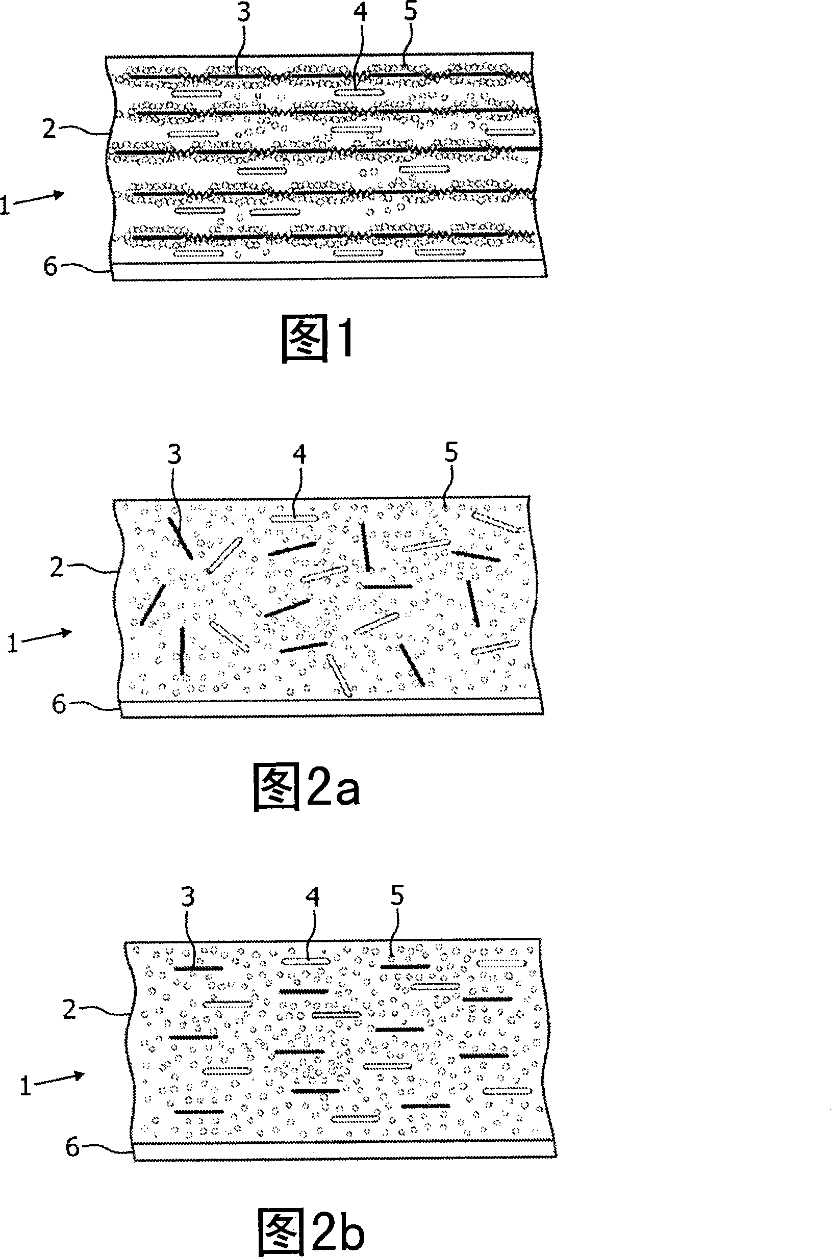
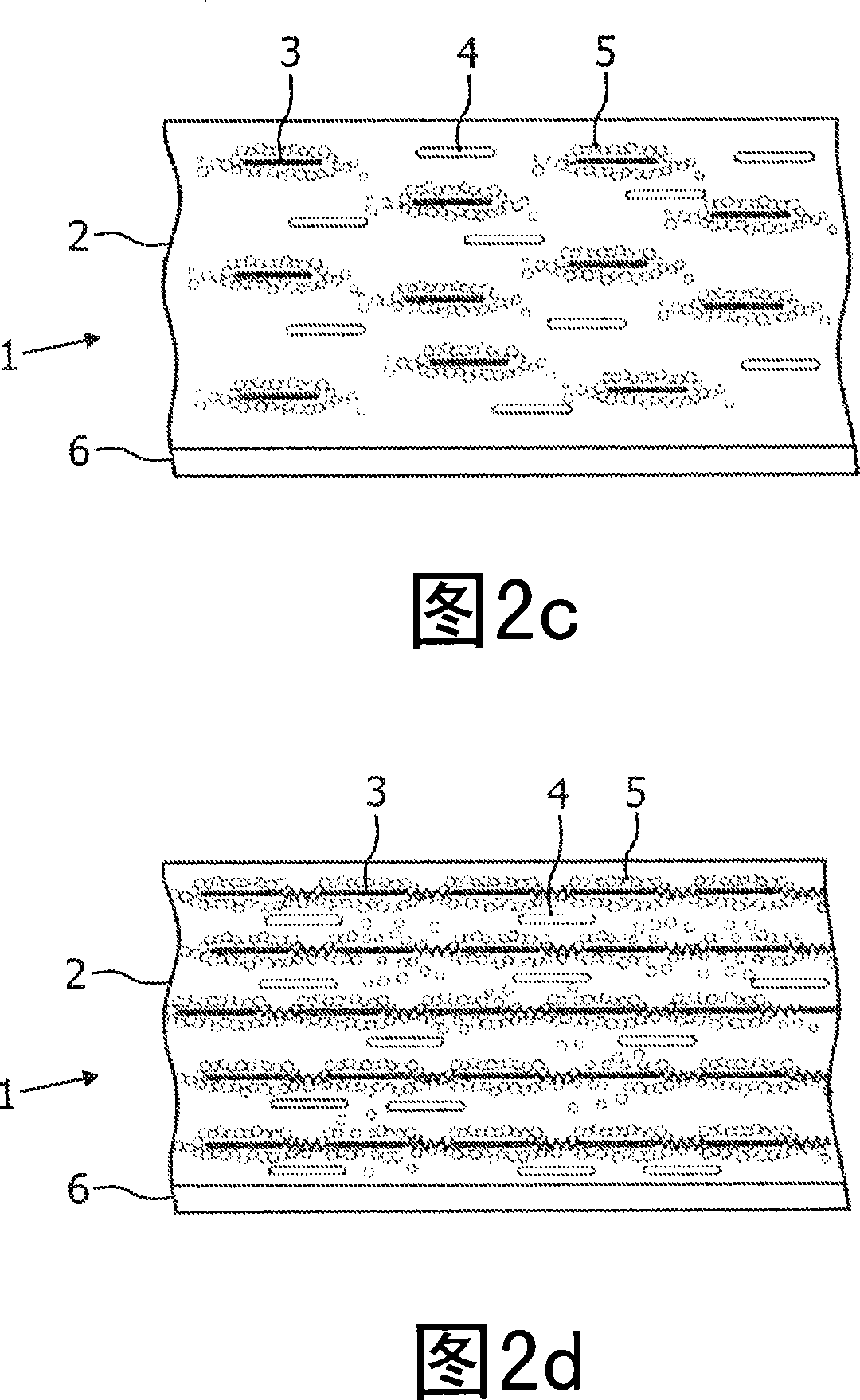
  • Dichroic guest-host polarizer
  • Dichroic guest-host polarizer
  • Dichroic guest-host polarizer

Examples


Embodiment Construction

[0125] Experiment 1

[0126] (not according to the invention)

[0127] A 33% by weight 50 / 50 mixture of the following smectic reactive mesogens V and VI was prepared (1% dichroic dye (NKX2029, Nippon Kankoh Shikiso Kenkyusho), 1% initiator (Irgacure 651, Ciba), 2% surface Active agent and 0.1% inhibitor (p-methoxyphenol)) in chlorobenzene.

[0128]

[0129] The solution was thus spin-coated on a substrate with a rubbed polyimide alignment layer to form a film about 2 microns thick.

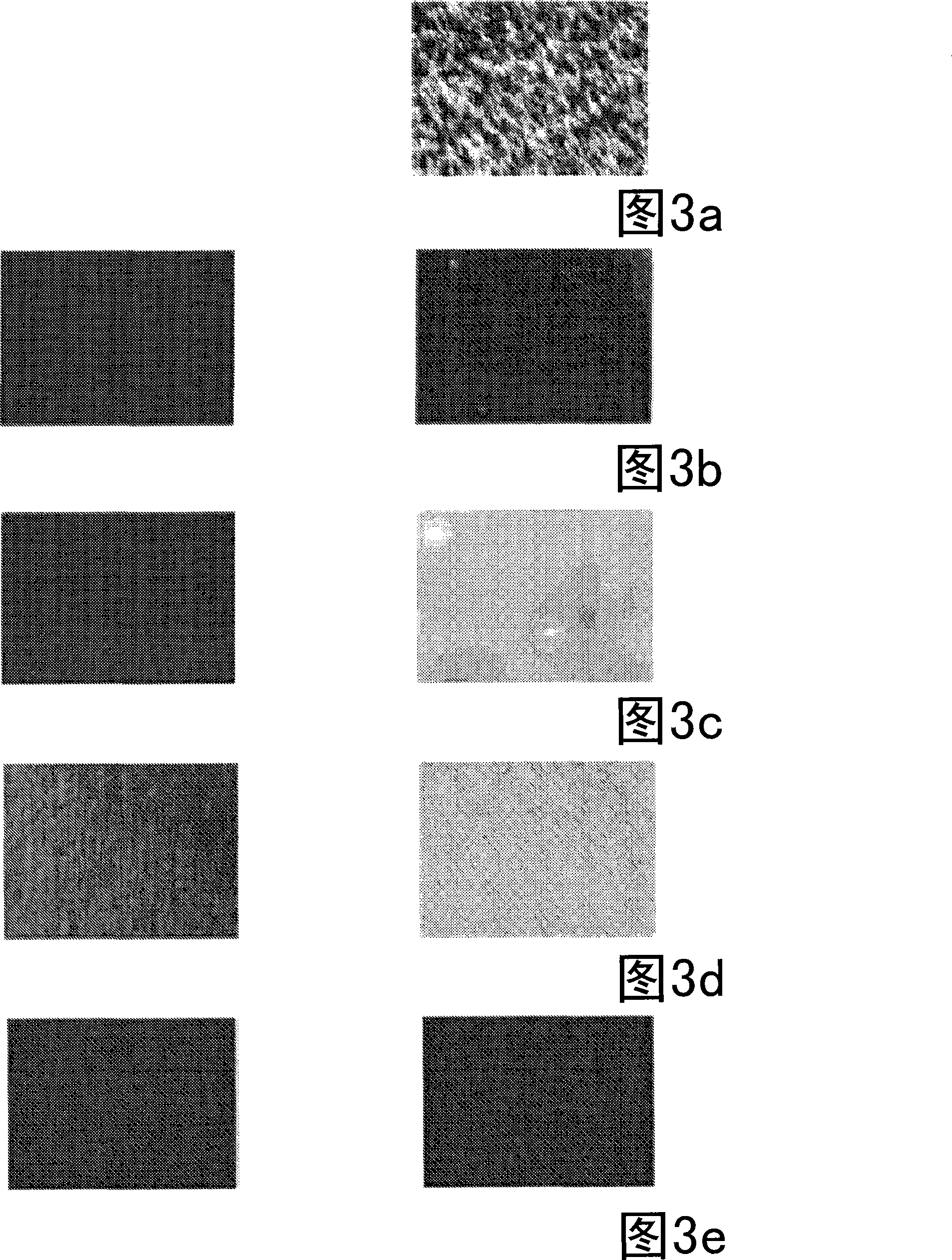
[0130]Figure 3 depicts micrographs of films obtained immediately after spin coating placed between crossed polarizers and at different temperatures. The micrograph on the right shows the image recorded at an angle of 45° between the director of the alignment layer and the polarizer, and the image on the left shows the image recorded at an angle of 0°.

[0131] Immediately after spin-coating, a multi-domain film is obtained in which the orientation of the liquid crystal substrates is predo...


PUM


Abstract

A method for the manufacture of a polarizer is provided. The method comprises providing a liquid crystal composition comprising a liquid crystal host and a viscosity enhancer; providing a thin film of said composition on a substrate; orienting said liquid crystal host to obtain an aligned film in a first liquid crystal mesophase, wherein the liquid crystal host is aligned planar to said substrate; gelating said viscosity enhancer to congeal said film; and obtaining a second liquid crystal state in said congealed film. By the use of a viscosity enhancer in the composition, homeotropic alignment of the liquid crystal host can be suppressed.

Description

Background technique [0001] Polarizers are widely used in a number of different applications requiring polarization of light. Currently, the most widely used polarizers in LCD applications are various derivatives of the H-polarizer sheet invented by E.H. Land in 1938. These dichroic polarizers consist of uniaxially stretched poly(vinyl alcohol) impregnated with iodine or coated with a dichroic dye. The wettable poly(vinyl alcohol) film is protected on both sides by a TAC-layer (triacetylcellulose). On one side of the film, an adhesive was used to laminate the polarizer to the display. The total thickness of the polarizer stack is about 70-150 μm. [0002] There is a need in the art for polarizers that can produce comparable or even greater polarization selectivity than H-sheet polarizers, but that are much thinner than H-sheet polarizers. And there is also a need for polarizers that can be conveniently used inside liquid crystal cells. [0003] These and other goals can b...

Claims


Application Information

Patent Timeline
IPC IPC(8): G02B5/30C09K19/52C09K19/60
CPCG02B5/3016C09K19/60C09K19/54C09K2019/526C09K19/52G02B5/30G02F1/13363
Inventor E·佩特斯D·J·布勒尓
Owner SUMITOMO CHEM CO LTD
Learn More