Air/fuel ratio control device for internal combustion engine

一种控制装置、空燃比的技术,应用在发动机控制、燃料喷射控制、电气控制等方向,能够解决性能变差、转矩变动增加、驾驶性能差等问题

Inactive Publication Date: 2008-07-02
MITSUBISHI ELECTRIC CORP
View PDF2 Cites 14 Cited by
  • Summary
  • Abstract
  • Description
  • Claims
  • Application Information

AI Technical Summary

Problems solved by technology

[0014] Existing air-fuel ratio control devices for internal combustion engines, such as those described in Patent Document 1, have the problem that the amplitude or cycle of air-fuel ratio vibration needs to be greatly changed with the maximum oxygen absorption amount, so the air-fuel ratio feedback performance and Torque fluctuations have a large influence, making the air-fuel ratio control performance poor
[0015] Furthermore, when the amplitude or period of the air-fuel ratio vibration becomes large, there are problems in that the performance of converging to a steady state when disturbance occurs is poor, and the exhaust performance during acceleration or deceleration is poor.
[0016] Torque fluctuations occur due to changes in the air-fuel ratio, and when the amplitude or period changes greatly, the drivability is poor and the marketability is reduced. Therefore, it is difficult to combine the conditions for vibration processing of the oxygen absorption amount with the setting conditions that emphasize feedback performance and those that emphasize torque. Tasks set separately from setting conditions
[0017] In order to adapt to the exhaust gas regulations of various settings in the world, it is necessary to change the catalyst according to the regulations of each country and region, and make various changes in the maximum oxygen absorption. Therefore, it is necessary to set the amplitude or period of air-fuel ratio vibration for each catalyst, and there is an appropriate Topics with high cost
In addition, there are various exhaust gas regulations for diagnosing catalyst deterioration, and there is a problem of adapting the amplitude and cycle of air-fuel ratio vibration according to the regulations of each country and region.
[0018] In addition, in recent years, the awareness of the global environment has increased, so regulations on exhaust gas have been strengthened, and in order to detect relatively slight catalyst degradation (decrease in the maximum oxygen absorption capacity), it is required to set the period or amplitude of the air-fuel ratio vibration to be large. Problems leading to various performance deterioration trends such as poor air-fuel ratio feedback performance and increased torque fluctuations
[0019] Recently, the heat resistance of substances capable of absorbing oxygen is increasing year by year, and the amount of addition to the catalyst may increase. Therefore, the maximum oxygen absorption capacity increases. It is required to set the period or amplitude of the air-fuel ratio vibration as large as possible, so there are problems that may cause Issues related to various performance deterioration trends such as poor air-fuel ratio feedback performance and increased torque fluctuations

Method used


Image

  • Air/fuel ratio control device for internal combustion engine
  • Air/fuel ratio control device for internal combustion engine
  • Air/fuel ratio control device for internal combustion engine

Examples


Embodiment approach 1

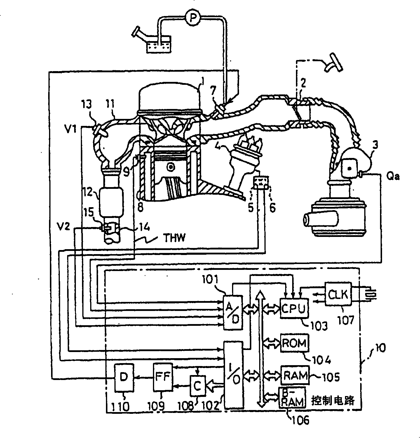
[0061] figure 1 It is a configuration diagram schematically showing an air-fuel ratio control device for an internal combustion engine according to Embodiment 1 of the present invention.

[0062] figure 1 Among them, an airflow sensor 3 is provided in an air intake passage 2 of a body 1 constituting an internal combustion engine (engine). The air flow sensor 3 has a built-in hot wire for directly measuring the intake air volume of the main body 1, and generates an output signal (analog voltage) proportional to the intake air volume. The output signal of the airflow sensor 3 is supplied to a multiplexer type analog-to-digital converter 101 in a control circuit 10 composed of a microcomputer.

[0063] The main body 1 is provided with a distributor 4 associated with ignition control of a plurality of cylinders, and the determiner 4 is provided with crank angle sensors 5 and 6 . One crank angle sensor 5 generates reference position detection pulses every 720 degrees in terms ...

Embodiment approach 2

[0364] Furthermore, in the first embodiment, the average air-fuel ratio vibration unit 203 performs the vibration processing based on the period counter Tmr, but may also perform the vibration processing based on the estimated value of the oxygen absorption amount (estimated oxygen absorption amount OSC).

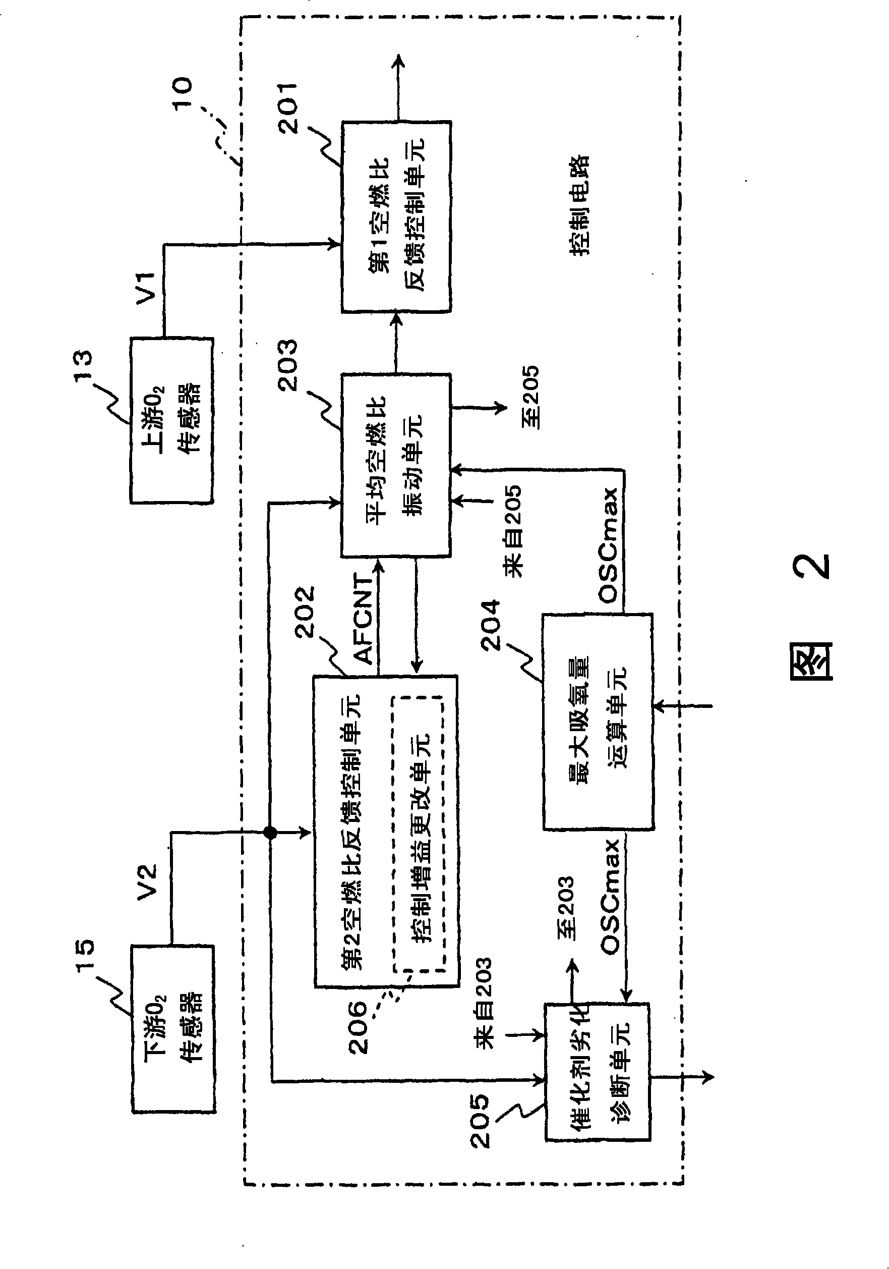
[0365] Below, refer to figure 1 and Figure 2 and Figure 28 ~ Figure 31 , to describe Embodiment 2 of the present invention in which vibration processing based on the estimated oxygen uptake OSC is performed. At this time, only the arithmetic processing of the average air-fuel ratio vibration unit 203 (refer to Figure 6 ), the overall composition and other functions of the air-fuel ratio control device of the internal combustion engine are the same as those described above.

[0366] Figure 28 is a flow chart showing the processing operation of the average air-fuel ratio vibration unit 203 according to Embodiment 2 of the present invention, and Figure 6 The same time...


PUM


Abstract

The invention discloses an air-fuel ratio control device for an internal combustion engine, which can freely change the oxygen absorption amplitude without changing the period and amplitude of the air-fuel ratio vibration that emphasizes the air-fuel ratio feedback performance and torque variation, so as to adapt to or diagnose catalyst degradation. Equipped with: According to the output value (V1) of the upstream air-fuel ratio sensor (13) and the specified control constant, adjust the air-fuel ratio of the main body (1) of the feeder, and make the air-fuel ratio periodically vibrate in the rich direction and the lean direction. An air-fuel ratio feedback control unit (201); and operate the control constant according to the oxygen absorption amount of the catalyst, so that the average air-fuel ratio obtained after averaging the periodically vibrating air-fuel ratio vibrates toward a rich direction and a lean direction. Vibration unit (203).

Description

technical field [0001] The present invention relates to an air-fuel ratio control device for an internal combustion engine mounted on a vehicle, and more particularly to an air-fuel ratio control device for an internal combustion engine provided with an air-fuel ratio feedback control unit for periodically vibrating the air-fuel ratio supplied to the internal combustion engine in a rich direction and a lean direction. Background technique [0002] On the exhaust passage of the internal combustion engine, it is generally installed to simultaneously purify the harmful components HC, CO, and NO in the exhaust gas. x The three-way catalyst (hereinafter referred to as "catalyst"). In this catalyst, the harmful components HC, CO, NO near the theoretical air-fuel ratio x Both have high purification rates. Therefore, in the air-fuel ratio control device of the internal combustion engine, the O 2 The sensor adjusts the fuel injection amount and performs feedback control on the air...

Claims


Application Information

Patent Timeline
Patent Type & Authority Applications(China)
IPC IPC(8): F02D41/14F01N11/00
CPCF01N3/10F01N11/007F02D41/0295F02D41/1408F02D41/1441F02D41/22
Inventor 田洼英树
Owner MITSUBISHI ELECTRIC CORP
Why Eureka
Try Eureka