Combined fuel pump device

A technology of fuel pump and oil pump, which is applied in the direction of charging system, liquid fuel feeder, adding non-fuel substances into fuel, etc., which can solve the problems of low efficiency of collecting fuel vapor and inconvenient installation of external fuel evaporation collection system, etc., to achieve Save external space, compact structure, and reduce emissions

Inactive Publication Date: 2008-07-02
BYD CO LTD
View PDF0 Cites 2 Cited by
  • Summary
  • Abstract
  • Description
  • Claims
  • Application Information

AI Technical Summary

Problems solved by technology

[0005] The purpose of the present invention is to overcome the disadvantages of inconvenient installation of the external fuel vapor collection system and low efficiency of collecting fuel vapor

Method used


Image

  • Combined fuel pump device
  • Combined fuel pump device
  • Combined fuel pump device

Examples


Embodiment Construction

[0015] Preferred embodiments of the present invention will be described in detail below in conjunction with the accompanying drawings.

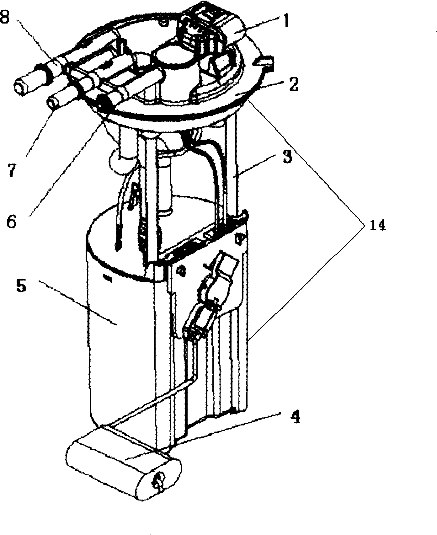
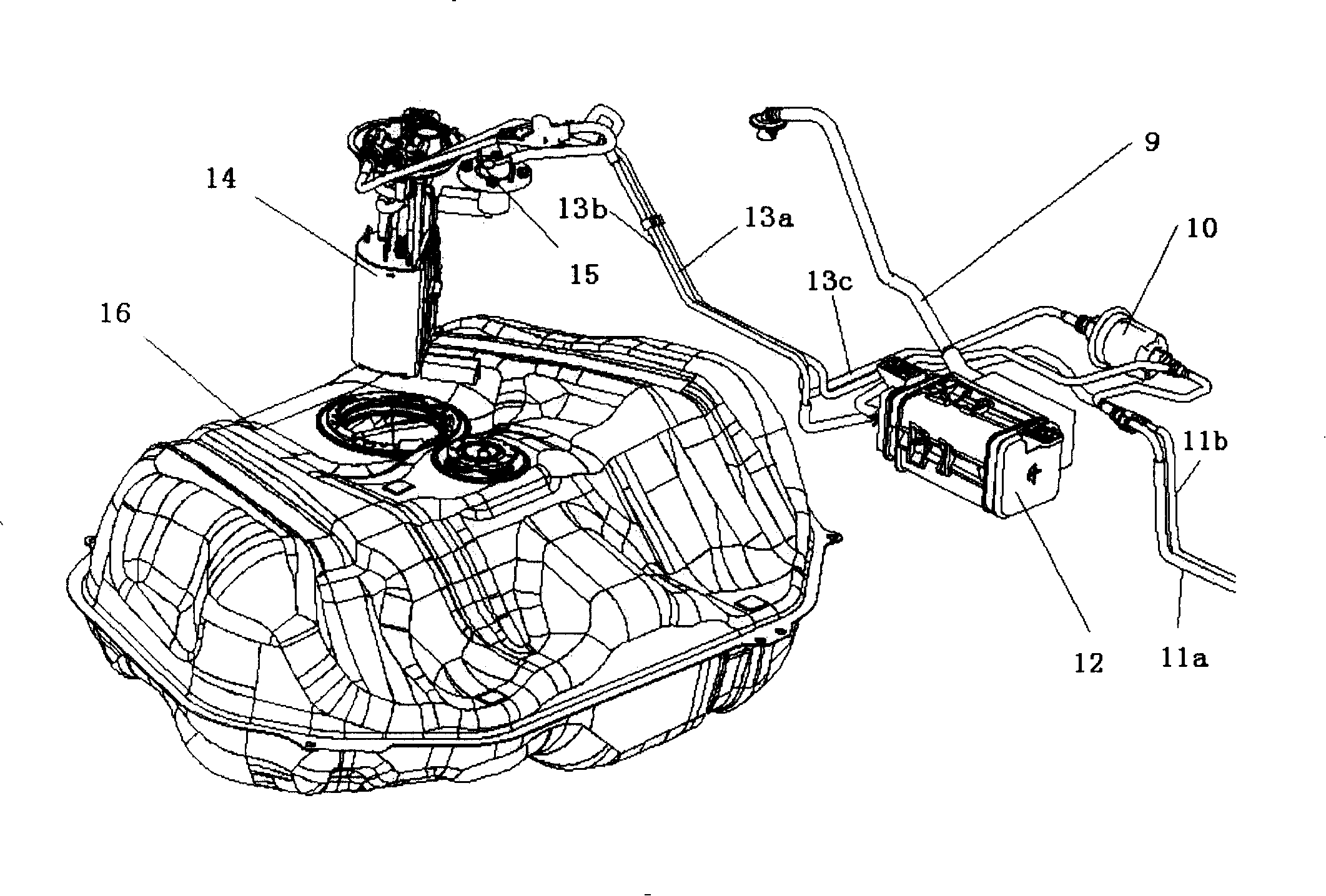
[0016] figure 1 Shown is a common electric fuel pump, the oil pump motor circuit connector 1 of the fuel pump 14 is located on the upper end surface of the flange 2, the flange 2 is connected with the oil pump body 5 through a metal rod 3, and is mounted on the side of the oil pump body 5 A liquid level sensor 4, an oil supply pipe joint 8, an oil return pipe joint 7, and a fuel vapor pipe joint 6 are respectively located on the upper end surface of the flange 2. Such as figure 1 , figure 2 As shown, the ordinary electric fuel pump 14 is installed inside the fuel tank 16 through the flange 2, the fuel pipe joint 8 is connected to the fuel supply pipe 13b, one end of the fuel filter 10 is connected to the fuel supply pipe 13b, and the other end is connected to the fuel supply pipe 11b and the oil return pipe 13c, the oil return pipe 13c is...


PUM


Abstract

A combined fuel pump unit comprises a fuel pump, an activated carbon canister, a fuel-steam communication cavity and an air cleaning device; wherein the activated carbon canister is fixed on the bottom end surface of the flange of the fuel pump, and the air cleaning device and the fuel-steam communication cavity are fixed on the top end surface of the flange of the fuel pump; the activated carbon canister is communicated with a connector of a steam pipe on the top end surface of the flange of the fuel pump, the air cleaning device and the fuel-steam communication cavity; and the fuel-steam communication cavity is used for the communication between the activated carbon canister and an oil tank. The combined fuel pump unit provided by the invention is a device which is compact in structure, convenient to installation and efficient in collecting fuel steam.

Description

technical field [0001] The invention relates to a fuel pump for vehicles. In particular, a combined fuel pump device for vehicles. Background technique [0002] The electric fuel pump is one of the basic components of an electronically controlled fuel injection engine. Such as figure 1 An ordinary electric fuel pump is shown, which is generally driven by a small DC motor. Its function is to suck the fuel out of the fuel tank, pressurize it and deliver it to the pipeline, and cooperate with the fuel pressure regulator to establish a suitable system pressure. Such as figure 2 As shown, the electric fuel pump is installed inside the fuel tank and soaked in fuel, and the fuel supply pipeline connected to the outside of the electric fuel pump has a fuel filter for filtering the fuel supplied to the engine. [0003] About 20% of the emissions produced by cars come from the evaporation of fuel. The fuel evaporation collection system can store the fuel vapor generated by the f...

Claims


Application Information

Patent Timeline
Patent Type & Authority Applications(China)
IPC IPC(8): F02M37/14F02M25/08
Inventor 何鹏谢伟冉猛
Owner BYD CO LTD
Why Eureka
Try Eureka