3 freedom degree high precision positioning movement device and positioning method

A technology for locating motion tables and positioning methods, which is applied to workbenches, instrument parts, instruments, etc., can solve problems such as lack of clear instructions, positioning dead zones, and small ranges, and achieve simple and reasonable positioning steps. High positioning accuracy and the effect of eliminating dead zones

Active Publication Date: 2008-07-02
SHANGHAI MICRO ELECTRONICS EQUIP (GRP) CO LTD
View PDF2 Cites 9 Cited by
  • Summary
  • Abstract
  • Description
  • Claims
  • Application Information

AI Technical Summary

Problems solved by technology

[0002] At present, in the traditional method of precise positioning of the workbench with three degrees of freedom (horizontal direction, vertical direction, and degree of rotation), because there is a zero-return dead zone for positioning, the zero-position sensor is generally installed in the motion stroke of the motor. One section, and close to its limit position, at the same time, through the mechanical device, the motor is on the side of the zero position sensor, the structure is complicated, and the effect of the zero return positioning of the limit position is not ideal
[0003] In addition, because the positioning of the logical axis Rz of the rotation angle in the current positioning method is only to find the zero position of the two physical axes Y1 and Y2 that make up the logical axis Rz, instead of finding the zero position at the same time, because each return Different zero conditions will generally produce different results; thus, it is easy to cause a large error for the positioning on this degree of freedom, and the positioning accuracy is not high
[0004] For example, Chinese Patent No. 03260236.7 discloses a three-degree-of-freedom precision positioning workbench, which mainly explains the structural design of the precision positioning workbench. The precision positioning method does not involve any new technical features, and still relies on traditional methods. , so that the repeated positioning of the workbench cannot be effectively guaranteed, and the three degrees of freedom (horizontal direction, vertical direction, and rotation degree) has a smaller range
[0005] Another example is Chinese Patent No. 200420046154.6, which also discloses a precision positioning platform. What is introduced in this patent is the mechanical structure and design method of the positioning platform, but there is no clear explanation for the precise positioning method, so The positioning method of the precision positioning platform still uses the traditional method, which has the disadvantages of low positioning accuracy and dead zones during positioning.

Method used


Image

  • 3 freedom degree high precision positioning movement device and positioning method
  • 3 freedom degree high precision positioning movement device and positioning method
  • 3 freedom degree high precision positioning movement device and positioning method

Examples


Embodiment approach

[0066] As shown in Figure 16, the three-degree-of-freedom high-precision positioning motion platform device provided by the present invention includes a motion platform 7, and is characterized in that it also includes:

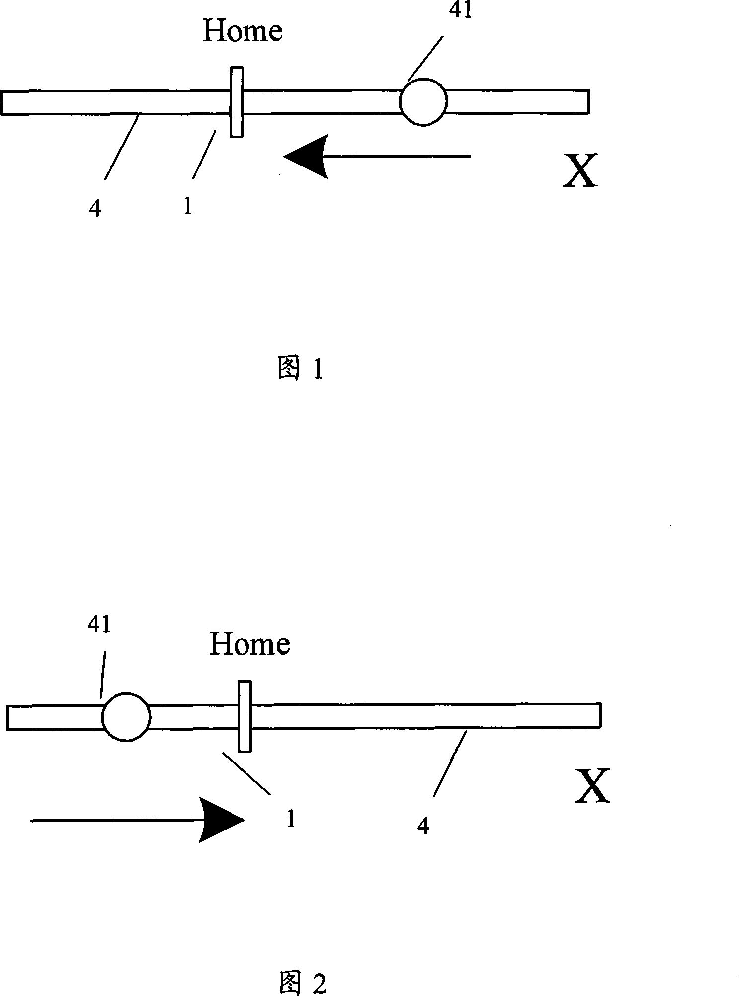
[0067] A horizontal lead screw motor 4, which is arranged along the horizontal X direction of the motion platform 7, and is connected to the vertical side of the motion platform 7; a horizontal Home position sensor 1 is correspondingly arranged along the direction in which the horizontal lead screw motor 4 is set;

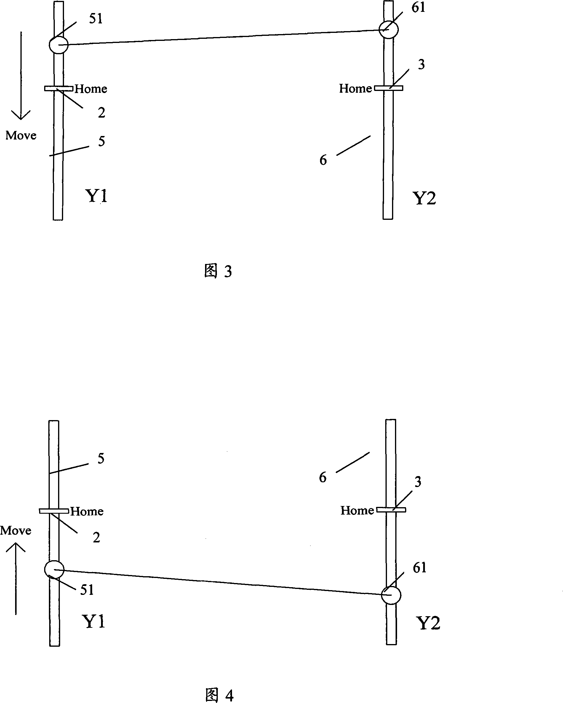
[0068] The first vertical lead screw motor 5 is arranged along the vertical Y direction of the motion platform 7 and is connected to the horizontal side of the motion platform 7; along the setting direction of the first vertical lead screw motor 5, a first vertical Home is correspondingly arranged. position sensor 2;

[0069] The second vertical lead screw motor 6, which is arranged along the vertical Y direction of the moving platform 7, is connec...

Embodiment 1

[0105] In this embodiment 1, first adjust the coordinate position of the motor encoder 41 on the horizontal X direction of the motion table device to as shown in Figure 1, and adjust the coordinate positions of the two motor encoders 51 and 61 in the vertical Y direction Adjust it as shown in Figure 3, and then start the three motors for servo control; the specific process of positioning the motion platform device is as follows:

[0106] Step 1. Measure and obtain the relative positional relationship between the encoders on each lead screw motor and its corresponding Home position sensor as described above, that is, the coordinate positional relationship of the current moving table device in the horizontal X direction and vertical Y direction is as follows: Shown in Figure 1 and Figure 3;

[0107] Step 2, as shown in Figure 1, since the horizontal encoder 41 is located on the right side of the horizontal Home position sensor 1, then move the motion platform 7 to the left until...

Embodiment 2

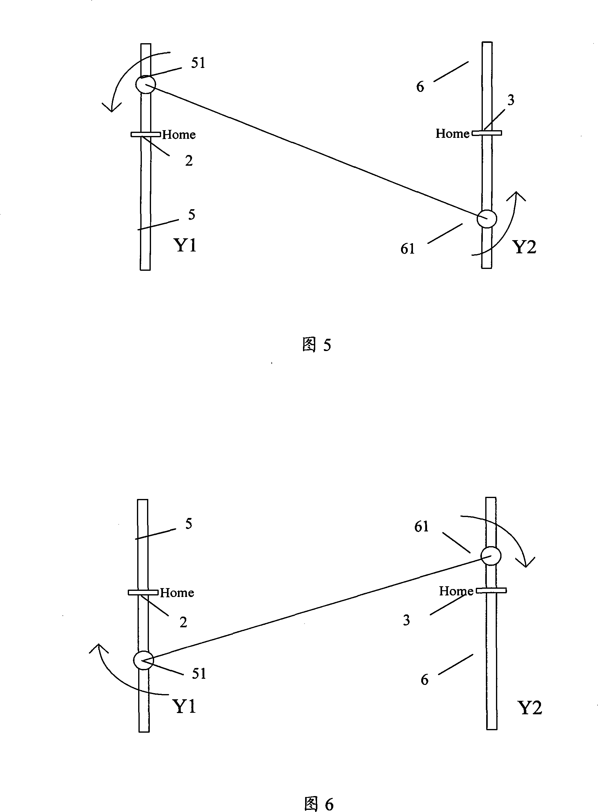
[0115] In this embodiment 2, first adjust the coordinate position of the motor encoder 41 on the horizontal X direction of the motion table device to as shown in Figure 2, and adjust the coordinate positions of the two motor encoders 51 and 61 in the vertical Y direction Adjust it as shown in Figure 5, and then start the three motors for servo control; the specific positioning process of the motion platform device is as follows:

[0116] Step 1. Measure and obtain the relative positional relationship between the encoders on each lead screw motor and its corresponding Home position sensor as described above, that is, the coordinate positional relationship of the current moving table device in the horizontal X direction and vertical Y direction is as follows: Shown in Figure 2 and Figure 5;

[0117] Step 2, as shown in Figure 2, since the horizontal encoder 41 is positioned at the left side of the horizontal Home position sensor 1, then move the motion platform 7 to the right un...


PUM


Abstract

The invention relates to a three-degrees-of-freedom high accuracy positioning motion bench device and a positioning method. The motion bench device comprises a motion bench, and further comprises a horizontal leading screw motor, a first vertical leading screw motor, a second vertical leading screw motor and Home position sensors which are arranged correspondingly. The positioning method of the motion bench device executes the coordinate zero position search positioning for the motion bench device by adopting the three-degrees-of-freedom coordinates calibration method of horizontal direction, vertical direction and rotation angle. The positioning method provided by the invention can realize the high accuracy of the level of micron and microradian during the repeated positioning, wherein the three-degrees-of-freedom directions have no positioning dead zone in the positioning process. At the same time, the positioning method provided by the invention is simple, reasonable and of lower implementing cost.

Description

technical field [0001] The invention relates to a three-degree-of-freedom high-precision positioning motion platform device and a positioning method, in particular to a three-degree-of-freedom high-precision zero-position search method for a motion platform through a coordinate system calibration method. Background technique [0002] At present, in the traditional method of precise positioning of the workbench with three degrees of freedom (horizontal direction, vertical direction, and degree of rotation), because there is a zero-return dead zone for positioning, the zero-position sensor is generally installed in the motion stroke of the motor. One section, and close to its limit position. At the same time, the motor is placed on one side of the zero position sensor through a mechanical device. The structure is complicated, and the effect of zeroing the limit position is not ideal. [0003] In addition, because the positioning of the logical axis Rz of the rotation angle in ...

Claims


Application Information

Patent Timeline
IPC IPC(8): G12B5/00B25H1/00
Inventor 张方元沈锦华陈锐
Owner SHANGHAI MICRO ELECTRONICS EQUIP (GRP) CO LTD
Why Eureka
Try Eureka