Hydraulic gyration tailstock

A tailstock and hydraulic technology, applied in the direction of tailstock/top, turning equipment, toolholder accessories, etc., can solve the problems of low work efficiency and labor, and achieve the effect of compact structure, high degree of automation and high precision

Inactive Publication Date: 2008-07-09
ANYANG XINSHENG MACHINE TOOL
View PDF0 Cites 15 Cited by
  • Summary
  • Abstract
  • Description
  • Claims
  • Application Information

AI Technical Summary

Problems solved by technology

Manually moving the tailstock spindle, one is

Method used


Image

  • Hydraulic gyration tailstock

Examples


Embodiment Construction

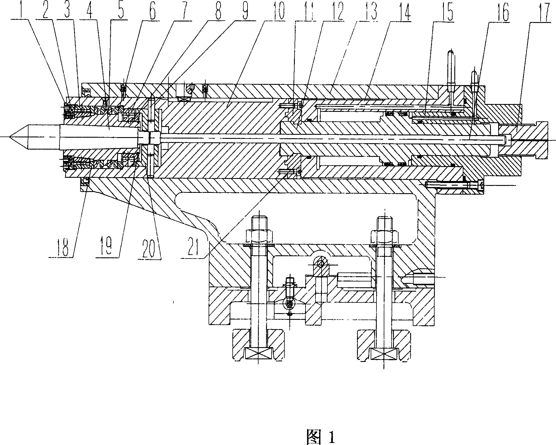
[0017] As shown in FIG. 1 , the present invention includes two oil chambers 14 , 15 of the piston cylinder designed on the rear end surface of the tailstock body 13 . Hydraulic pressure is used to drive the piston shaft 12 to move forward and backward. The piston shaft 12 is connected with the tailstock main shaft 10 through the fixing ring 11 and the screw 21, and the tailstock main shaft 10 and the piston shaft 12 move synchronously to realize the hydraulic automatic telescopic movement of the tailstock main shaft 10.

[0018] A tailstock sleeve supported by bearings is installed in the front hole of the tailstock main shaft to realize the rotatable performance of the tailstock sleeve. The specific structure is: the internal thread at the front end of the tailstock main shaft 10 is connected with the nut 1, and the right end surface of the nut 1 is close to the double row 3 outer rings of cylindrical roller bearings, 3 outer rings of double-row cylindrical roller bearings ar...


PUM


Abstract

The invention relates to a hydraulic rotary tailstock suitable for processing a rotary type heavy workpiece with high speed including a tailstock body, a hydraulic cylinder arranged at the back end surface of the tailstock. A piston shaft is arranged in the hydraulic cylinder and the piston shaft is driven to move forwards and backwards by hydraulic pressure. The piston shaft is connected with a main shaft of the tailstock as a whole body. The main shaft of the tailstock moves synchronously with the piston shaft. A front end hole of the main shaft of the tailstock is provided with a tailstock sleeve supported by a bearing. An inner taper of the tailstock sleeve is cooperated with an outer taper shank of a tip and connected as a whole body. When the workpiece rotates at a high speed, the rotation of the tip and the tailstock sleeve are realized. The invention has the advantages of good supporting performance, high automatization degree, high manufacture efficiency and excellent processing effect on the heavy workpiece requiring a high precision.

Description

Technical field: [0001] The invention relates to a lathe tailstock suitable for high-speed machining of rotary heavy workpieces, in particular to a hydraulic rotary tailstock with good supporting performance, high degree of automation, high production efficiency, and good effect on processing heavy workpieces with high precision requirements. seat. Background technique: [0002] At present, most of the tailstocks of machine tools manufactured by some domestic enterprises are of non-rotating structure, and the main shaft of the tailstock is manually moved. When processing heavy workpieces in high-speed rotation, the center sleeve cannot be rotated so that the dead center is easy to grind and burn. Due to the small structure, the live center has a short support arm, less internal support bearings, and limited load capacity. Manually moving the tailstock spindle, one is laborious, and the other is low work efficiency. Invention content: [0003] The purpose of the present ...

Claims


Application Information

Patent Timeline
IPC IPC(8): B23B23/00
Inventor 韩长生郑文喜权瑞霞郝利军
Owner ANYANG XINSHENG MACHINE TOOL
Why Eureka
Try Eureka