Plastic tap and its manufacture method

A manufacturing method and faucet technology, which are applied in the field of faucets, can solve the problems affecting the water outlet flow of the faucet, the extrusion deformation of the connecting pipe, etc., and achieve the effects of good water outlet effect, low cost and easy implementation.

Inactive Publication Date: 2008-07-09
吴兵
View PDF1 Cites 26 Cited by
  • Summary
  • Abstract
  • Description
  • Claims
  • Application Information

AI Technical Summary

Problems solved by technology

However, the plastic connecting pipe is used in this faucet, so that the connecting pipe will be squeezed and deformed during the injection molding process. After the plastic is solidified, the deformed connecting pipe will affect the water flow of the entire faucet

Method used


Image

  • Plastic tap and its manufacture method
  • Plastic tap and its manufacture method
  • Plastic tap and its manufacture method

Examples


Embodiment 1

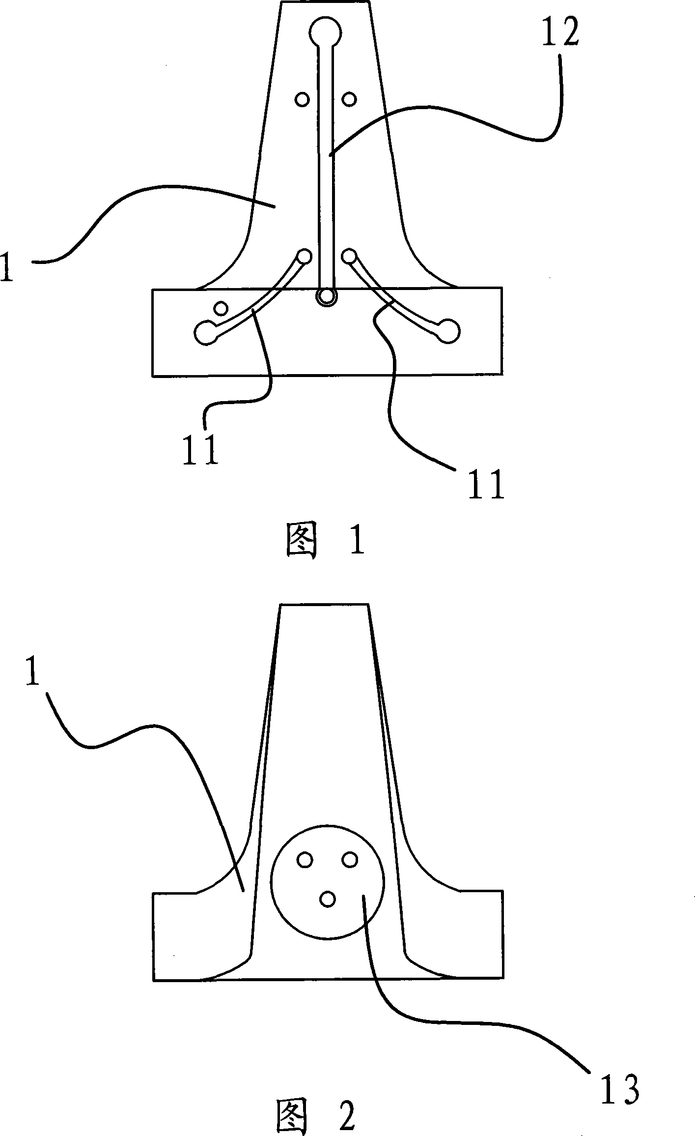
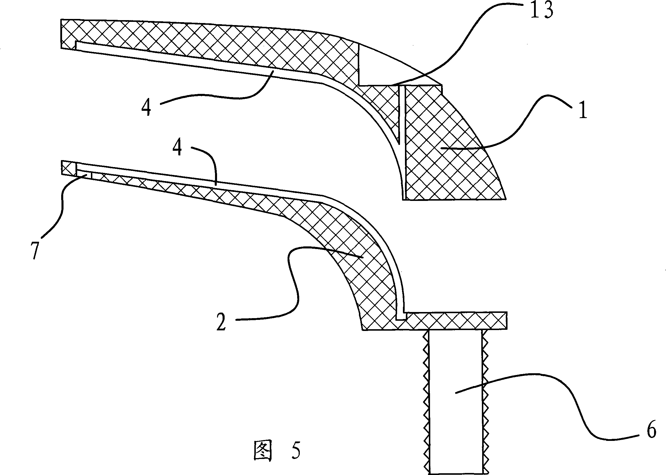
[0047] As shown in FIGS. 1 to 7 , the plastic faucet includes a body and a housing 5 tightly wrapped on the outside of the body.

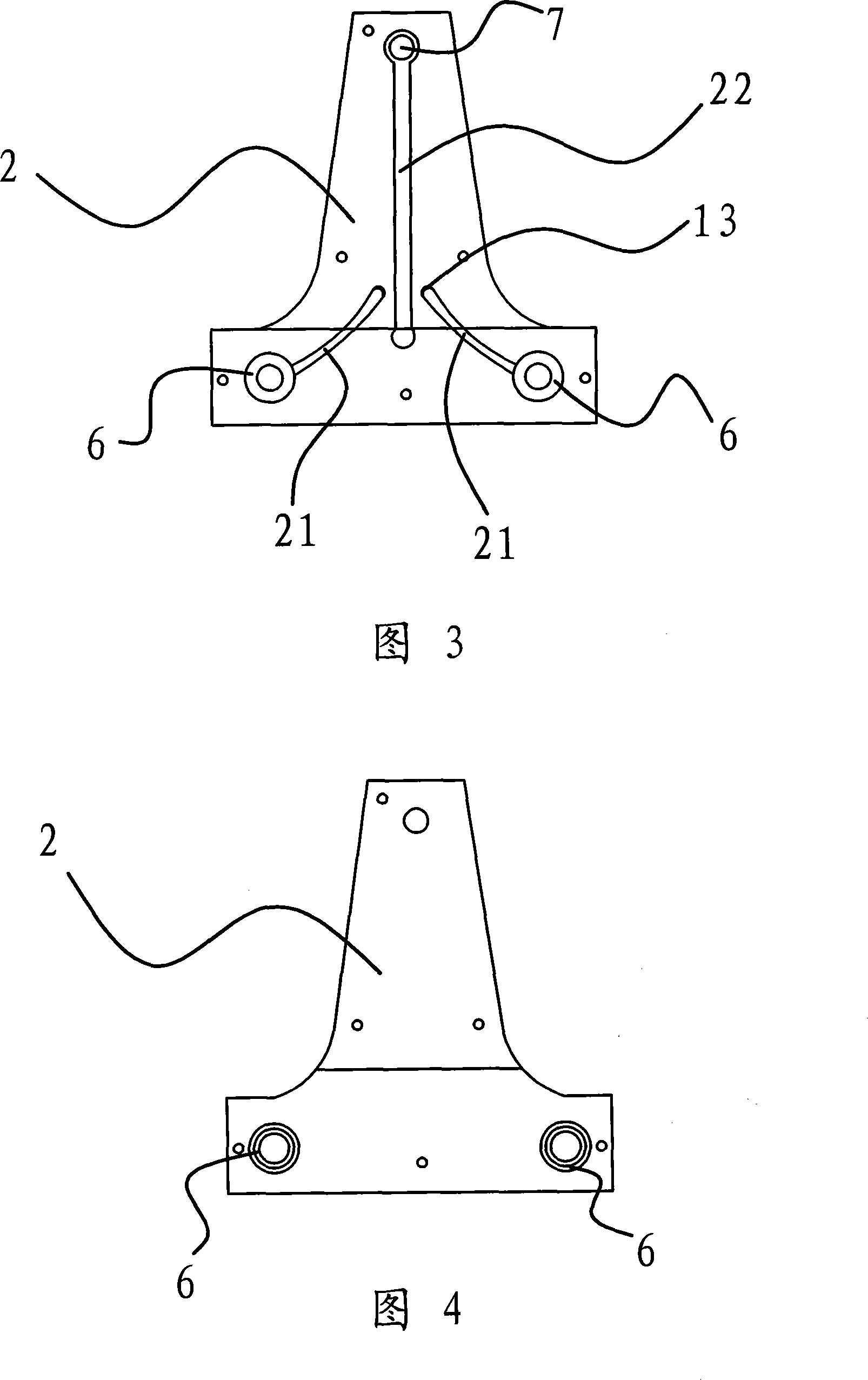
[0048]As shown in Figure 1 and Figure 2 and Figure 3 and Figure 4, the body consists of an upper body 1 and a lower body 2 connected together, the upper body 1 is superimposed on the upper part of the upper and lower body 2, and the upper body 1 is provided with an upper body Groove one 11, the lower body 2 is provided with a lower groove one 21, and the position of the upper groove one 11 is corresponding to the position of the lower groove one 21. At the same time, the upper body 1 is also provided with an upper groove 2 12, and the lower body 2 is also provided with a lower groove 2 22, and the positions of the upper groove 2 12 and the lower groove 2 22 are corresponding. Obviously, such a structure makes the upper groove one 11 and the lower groove one 21 form the water inlet channel 3 , and the upper groove two 12 and the lower groove two 22 ...

Embodiment 2

[0067] This embodiment is basically the same as Embodiment 1, except that the water inlet channel 3 is a through hole drilled directly on the lower body 2, and one end of the through hole communicates with the water inlet pipe 6 and the other end communicates with the valve core seat 13. Since the through hole is drilled directly, a straight hole-shaped water inlet channel 3 is formed, as shown in FIGS. 8 and 9 . Of course, according to the actual situation, the water outlet channel 4 can also be formed by drilling.

[0068] As shown in FIG. 8 , FIG. 9 , FIG. 10 and FIG. 11 and FIG. 12 , the upper body 1 is further provided with a card slot 14 , and the lower body 2 is provided with a card head 23 matching the shape of the card slot 14 . As shown in Figure 12, during the connection process of the upper body 1 and the lower body 2, the clamping head 23 can be matched directly through the slot 14, so that the positions of the upper body 1 and the lower body 2 are aligned, and at...


PUM


Abstract

The invention provides a plastic faucet and a manufacturing method thereof, which belongs to the technical field of life necessaries and solves the problems of prior art, such as difficult fabrication, high cost and poor stability in water outlet. The plastic faucet comprises a main body and a valve core, which are made of plastic materials. The external end of the valve core extends outside the main body and then is connected with a handle. The main body is also provided with a water inlet pipe and a water outlet port. The main body consists of an upper body and a lower body, which are overlapped together. A shell is arranged outside the upper body and the lower body to tightly enclose the two bodies. An inlet water passage and an outlet water passage are arranged at the junction of the upper body and the lower body and communicated with the water inlet pipe and the water outlet port respectively. The manufacturing method of the plastic faucet comprises the following steps: A. parts fabrication; B. parts assembly; C. mould setting and closing; D. injection molding; E. surface treatment; and F. assembly finishing. The invention has the advantages of simple structure, low cost, good stability in water outlet, and convenient fabrication and use.

Description

technical field [0001] The invention relates to a water faucet, especially a plastic water faucet, and a manufacturing method of the plastic water faucet. Background technique [0002] Faucets are usually made of metal materials. Specifically, the use of metal materials to make faucets is mainly that the body part of the faucet is cast and processed with metal materials, and then the valve core, valve stem, handle and other parts are put into the whole faucet to assemble and shape. Adopting this manufacturing method not only needs to consume a large amount of metal materials, but also because sand cores are used in the mold during the manufacturing process, these products will have sand holes and pores, and the defective rate is high. Therefore, the cost of faucets made of metal materials is relatively high, and the yield is relatively low. [0003] In order to solve the above problems, people have designed other non-metallic faucets, such as ceramic faucets and plastic fa...

Claims


Application Information

Patent Timeline
Patent Type & Authority Applications(China)
IPC IPC(8): F16K3/08F16K11/074F16K27/04B29C69/00B29C45/14B29C45/00B29C65/00
Inventor 吴兵
Owner 吴兵
Why Eureka
Try Eureka