Revolving furnace

A technology of rotary furnace and rotary drum, which is applied in the direction of rotary drum furnace, furnace, furnace type, etc., can solve the problems of unsuitable for small and medium-scale production requirements, large occupied area, high manufacturing cost, etc., and achieve small occupied area and low labor cost. The effect of low strength and easy operation

Inactive Publication Date: 2008-07-09
XIAN MODERN CHEM RES INST
View PDF5 Cites 21 Cited by
  • Summary
  • Abstract
  • Description
  • Claims
  • Application Information

AI Technical Summary

Problems solved by technology

The continuous rotary furnace is suitable for continuous production and is easy to operate, but it has disadvantages such as complex structure, high manufacturing cost, and large floor space, and is not suitable for small and medium-scale production requirements.
[0004] Chinese utility model patent CN2697459Y discloses an intermittent rotary kiln that can be used for roasting catalysts and carriers in small and medium scales, but manual loading and unloading is required

Method used


Image

  • Revolving furnace
  • Revolving furnace
  • Revolving furnace

Examples


Embodiment Construction

[0037] 1. Rotary furnace

[0038] Referring to Fig. 1, Fig. 2, Fig. 3, Fig. 4 and Fig. 5, the present invention will be described in further detail.

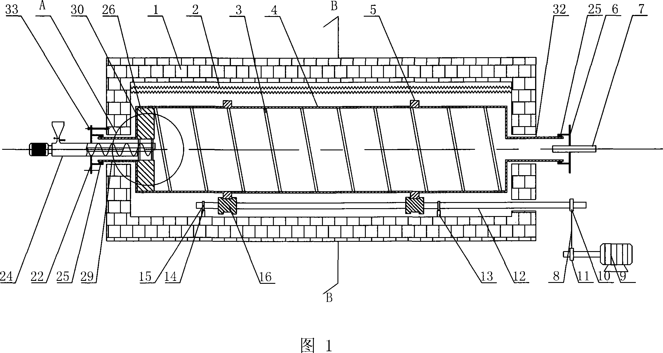
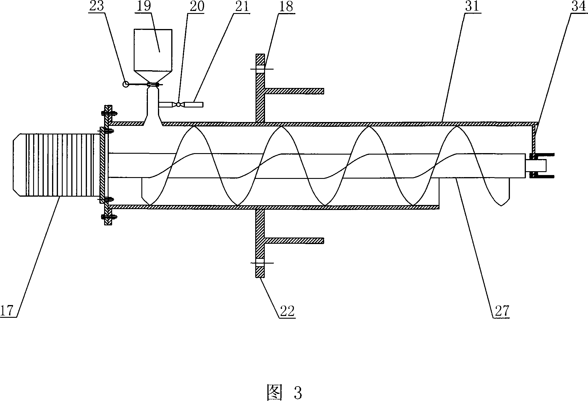
[0039] The rotary furnace of the present invention is composed of furnace body 1, rotary drum 4, feeding and discharging device 24, power drive device and other parts:

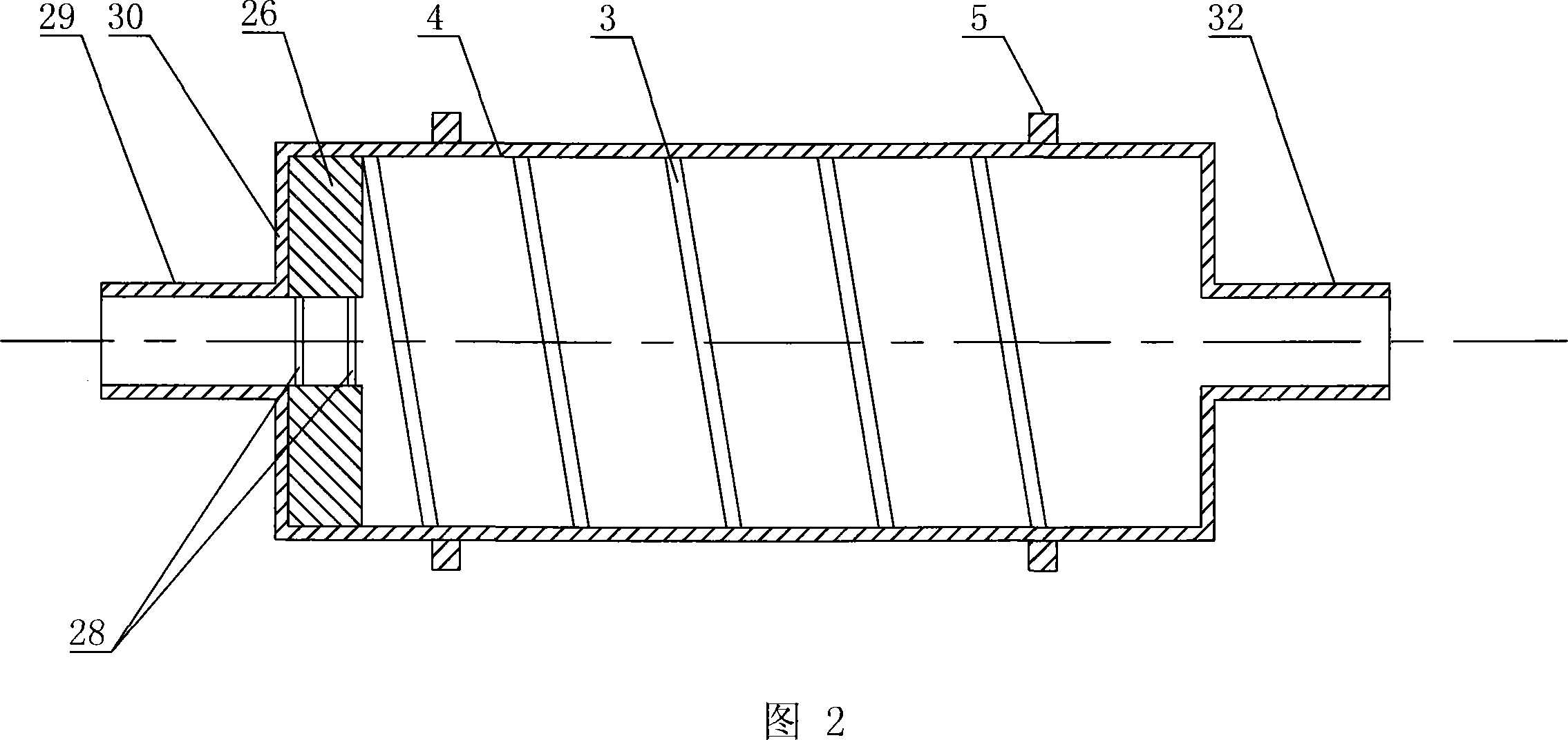
[0040] A. Rotary drum

[0041]The rotary cylinder 4 is located inside the furnace body 1 , and the material inlet and outlet end and the waste gas outlet end of the rotary cylinder pass through the furnace body 1 . The inner wall of the rotary drum 4 is welded with spiral baffles 3 equidistantly distributed, and its height is 1 / 20 of the diameter of the rotary drum; two symmetrical discharge guide plates 26 are welded radially at the inlet and outlet of the rotary drum. The guide plate 26 is a rectangular plate, and the adjacent two sides are welded to the end surface 30 of the inlet and outlet of the rotary drum and the inner wall respectively, and the inner ...


PUM


Abstract

The invention discloses a rotary furnace, aiming to solve manual feeding and discharging problem of the batch rotary furnace. The inventive rotary furnace comprises a rotary drum and a feeding and discharging device, wherein the feeding and discharging device is disposed at the feeding and discharging end of the rotary drum and extrudes into the rotary drum; spiral baffles are distributed on the inner wall of the rotary drum in equal interval, two symmetric discharge guide plates are disposed at the feeding and discharging end of the rotary drum in radial direction, and when feeding, a screw rod of the feeding and discharging device and the rotary drum perform forward rotation at the same time, so as to automatically feed to the rotary drum; when discharging, the rotary drum rotates in reverse direction, the materials in the rotary drum are introduced into the discharge device via the spiral baffles and the discharge guide plates, and the screw rod of the feeding and discharging device and the rotary drum perform reverse rotation at the same time, so as to automatically discharge. The inventive rotary furnace has the advantages of convenient feeding and discharging, simple structure, convenient operation, uniform material heating and low floor area; and is suitable for calcinating small or medium-scaled catalyst or carrier and high-temperature drying material.

Description

technical field [0001] The invention relates to a rotary kiln, in particular to a rotary kiln for catalyst or carrier roasting. Background technique [0002] At present, there are two main types of equipment used for catalyst and carrier roasting: one is static roasting equipment, such as muffle furnaces, tunnel kilns, etc., and its disadvantage is that materials are not heated evenly in a static state; the other is rotary kilns, and It is divided into intermittent rotary furnace and continuous rotary furnace. Because the rotary furnace can stir and mix the materials, the materials are heated evenly in it, so the roasting effect of the rotary kiln is better than that of the static roasting equipment, and the roasting of industrial catalysts and carriers. Most of the roasting equipment used is a rotary kiln. [0003] Chinese invention patents CN101026576A and CN101017057A disclose a continuous rotary kiln, through the rotation of the drum and the cooperation of the inclinati...

Claims


Application Information

Patent Timeline
Patent Type & Authority Applications(China)
IPC IPC(8): F27B7/22F27B7/32F27B7/33F27B7/08F27B7/26
Inventor 吕剑庞国川寇联岗张伟石磊崔文华何飞徐强郝志军
Owner XIAN MODERN CHEM RES INST
Why Eureka
Try Eureka