Angular displacement sensor

An angular displacement sensor and sensor technology, which is applied in the direction of using an electric/magnetic device to transmit sensing components, can solve the problems of difficult to ensure production consistency, difficult to meet accurate measurement, and difficult to process and produce, and achieve a reduction in shape and position tolerances. requirements, the magnetic field change rate is enhanced, and the effect of improving the linearity of the signal output

Inactive Publication Date: 2008-07-09
塞尔福(厦门)工业有限公司
View PDF2 Cites 16 Cited by
  • Summary
  • Abstract
  • Description
  • Claims
  • Application Information

AI Technical Summary

Problems solved by technology

However, these angular displacement sensors still have the following deficiencies: the structure is relatively complex, the processing and production are difficult, and the cost is high; or the linearity of the sensor s...

Method used


Image

  • Angular displacement sensor
  • Angular displacement sensor
  • Angular displacement sensor

Examples


Embodiment 1

[0053] Embodiment 1 of the present invention in the measurement of throttle body angular displacement will be described in detail below in conjunction with accompanying drawings 1 to 3 .

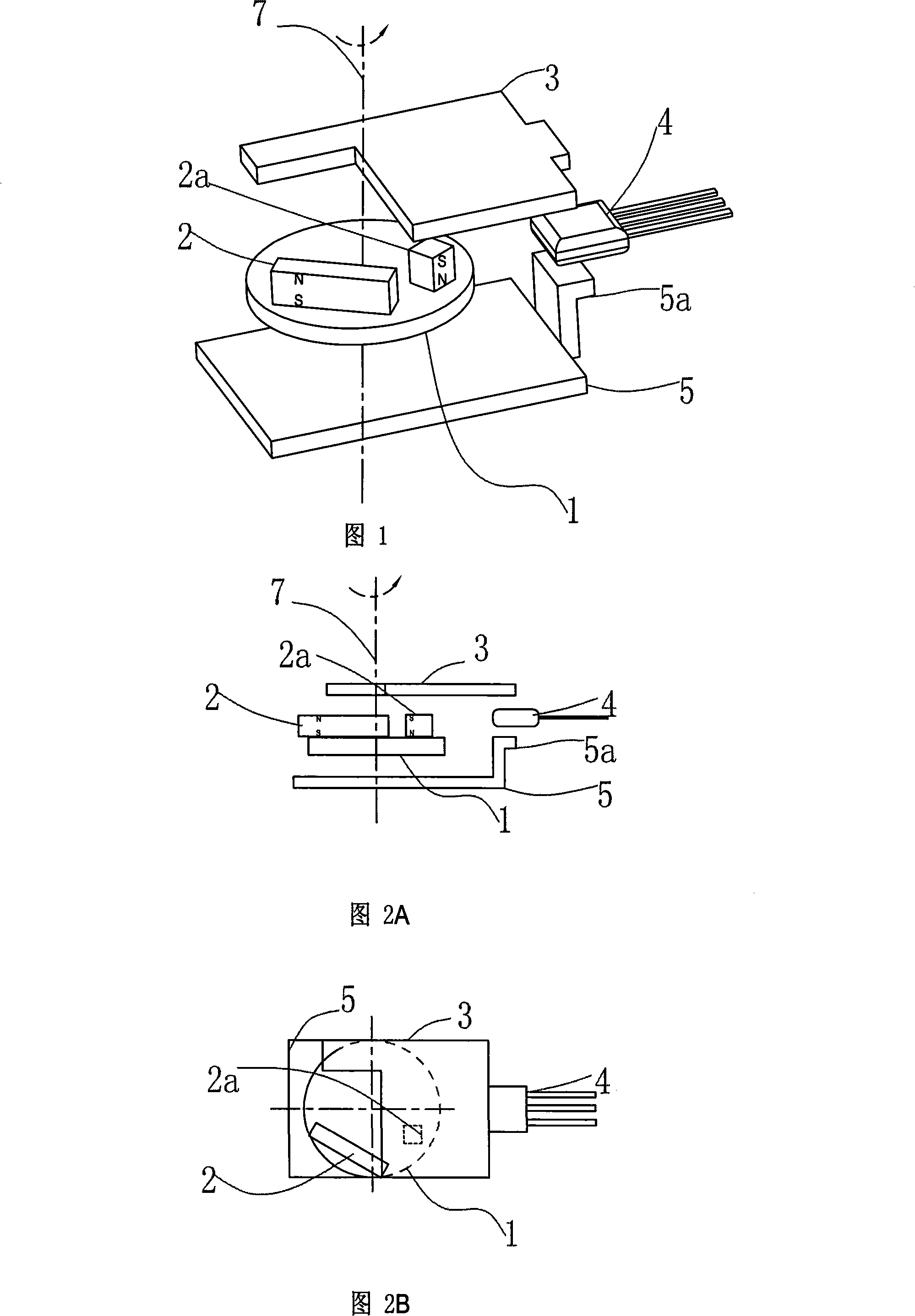
[0054] Fig. 1 is an axial view of Embodiment 1 of an angular displacement sensor.

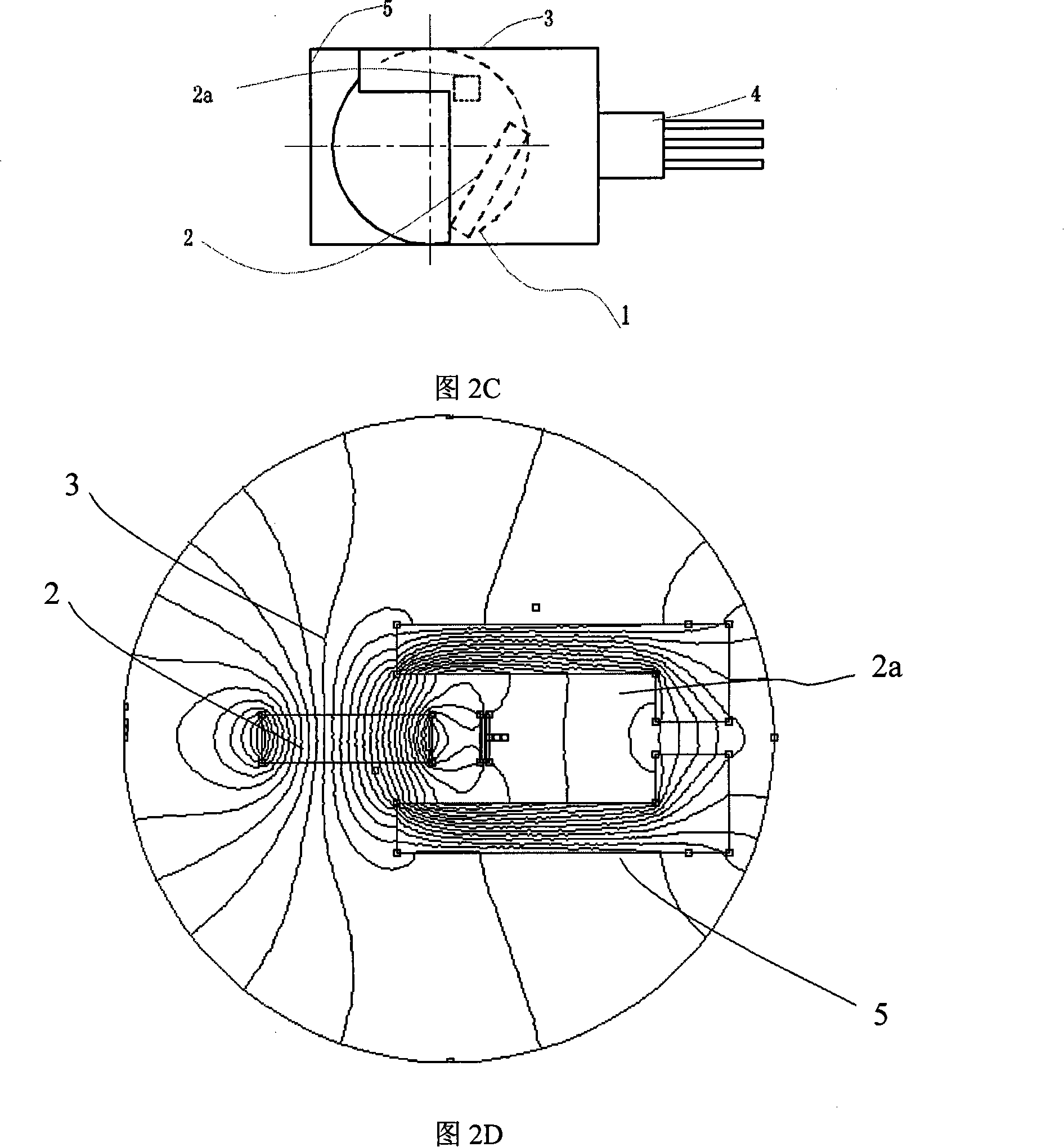
[0055]As shown in the figure, the rotating body 1 includes a magnetic element 2 and a reference magnetic element 2a; the magnetization directions of the magnetic element 2 and the reference magnetic element 2a are parallel to the rotation center of the rotating body, but the magnetization directions of the two are opposite, and their respective The polarity after magnetization is shown in Figure 2(A).

[0056] The sensor structure also includes an upper yoke 3 and a lower yoke 5; the lower yoke 5 has an upper protrusion 5a.

[0057] The Hall sensor 4 is installed between the parallel magnetic fields formed by the lower yoke 3 and the upper yoke 5 , and the magnetic flux detection direction of the Hall sensor...

Embodiment 2

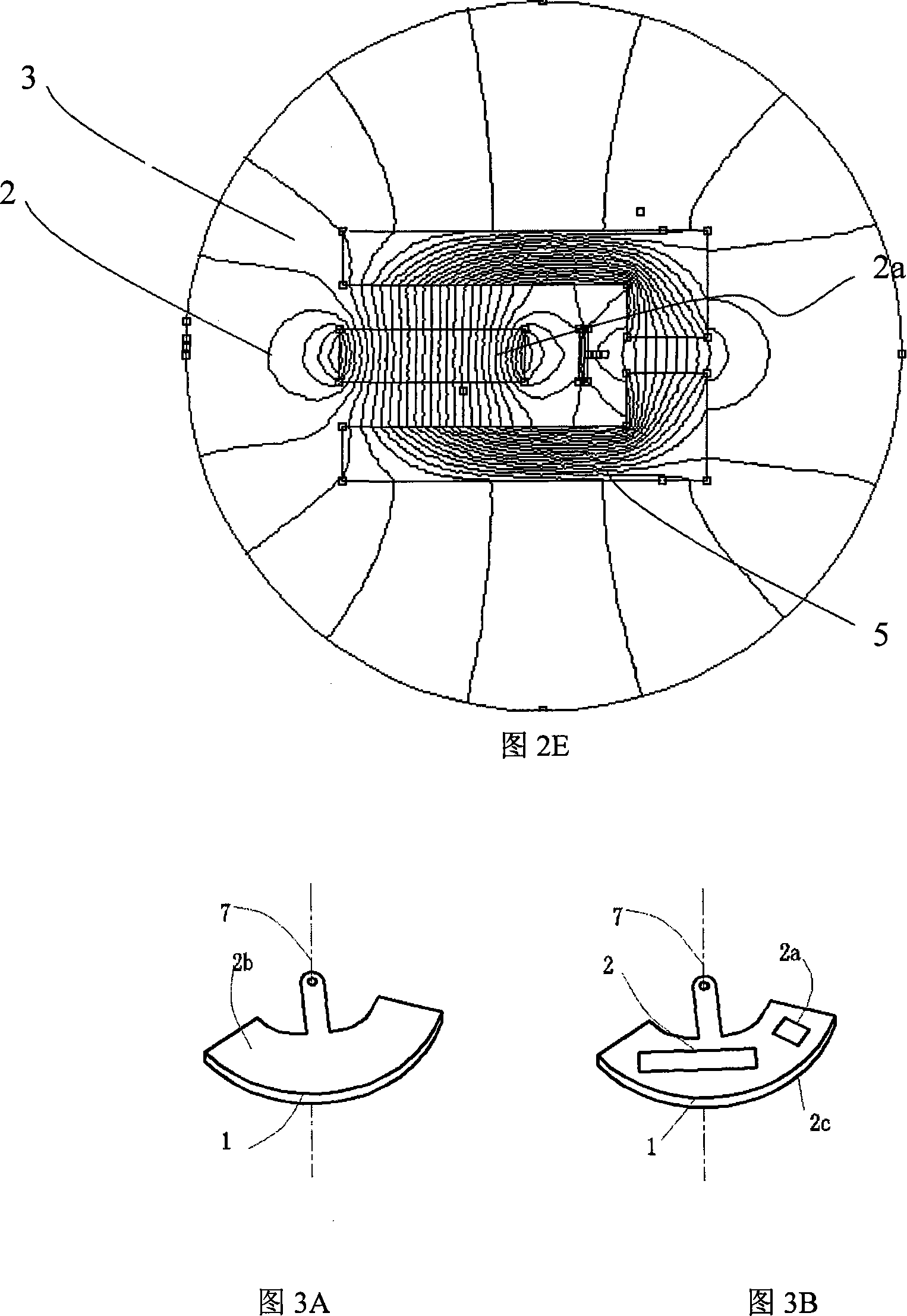
[0065] The difference from the first embodiment is that the addition of the lower protrusion 2b of the upper yoke can improve the sensitivity of the sensor and the linearity of the output signal. Fig. 5 is an axial view of an angular displacement sensor in the second embodiment. Fig. 6 is a side view of an angular displacement sensor in the second embodiment.

Embodiment 3

[0067] When the temperature stability of the magnetic element is good, or the temperature of the operating environment changes little, in order to further save costs, on the basis of the first embodiment, the reference magnetic element 2b is removed. At the same time, in certain occasions, in order to facilitate the axial installation of the lower yoke 5, the installation position of the magnetic detection element 4 is changed. This forms embodiment three. Fig. 7 is a side view of an angular displacement sensor in the third embodiment.

[0068] In order to simplify the product structure, improve the consistency of product production, improve the assembly reliability and manufacturability of the product, and greatly reduce the production cost, in this embodiment, the magnetic element 2b is made by injection molding or integral gluing, that is, the entire magnetic element 2b is made by injection molding. The magnetic element 2b is replaced by a molded or glued integrally formed...


PUM


Abstract

The invention relates to an angular displacement sensor, belonging to the technical field of magnetoelectric sensors. The sensor comprises a rotating member (1), wherein the rotating member (1) comprises a magnetic element (2) with magnetizing direction substantially parallel to the axial direction of the rotating member (1) thereof. The magnetic field generated by the rotating member (1) forms parallel and uniform magnetic field in the magnetic flux induction surface of a Hall sensor (4). When the rotating member (1) rotates, the increment of the magnetic intensity detected by the Hall sensor (4) is proportional to the angular increment in a wide angular region, so as to realize the measurement to the angular displacement. The inventive angular displacement sensor has the advantages of simple structure, low production cost, good signal stability, and highly linear and controllable signal conditioning.

Description

technical field [0001] The invention belongs to the technical field of detecting and sensing devices for detecting and sensing the position of a moving component by means of magnetoelectric transmission, and in particular relates to a non-contact angular displacement sensor composed of a combination of a magnetic element and a Hall sensor. Background technique [0002] In the field of automotive electronics, the principle of the traditional throttle opening sensor is to use a sliding potentiometer to convert the angular displacement into an electrical signal. The main problem of this sensor is that the contact part of the sliding potentiometer is prone to failure due to wear. Therefore, the To meet the need of using non-contact angular displacement sensor. There are many technical solutions for the angular displacement sensor of the non-contact magnetic induction element, such as the Chinese invention patent CN1769843A "non-contact rotation angle detection sensor", which is ...

Claims


Application Information

Patent Timeline
IPC IPC(8): G01D5/14
Inventor 张平郗大光刘小吉杨延相
Owner 塞尔福(厦门)工业有限公司
Why Eureka
Try Eureka