Powerline pole tower ground resistance measurement method and its tester

A grounding resistance and transmission line technology, applied in the high-voltage field, can solve problems such as affecting the measurement results, and achieve the effects of avoiding power frequency interference, accurate measurement, and convenient measurement

Active Publication Date: 2008-07-09
WUHAN NARI LIABILITY OF STATE GRID ELECTRIC POWER RES INST +1
View PDF0 Cites 24 Cited by
  • Summary
  • Abstract
  • Description
  • Claims
  • Application Information

AI Technical Summary

Problems solved by technology

Compared with the shaking meter method, this method does not need to be set out, and the measurement is more convenient. However, if the clamp-type contacts are not in tight contact during the measurement, and the existence of induced voltage, it is easy to generate large interference, which will affect the measurement results.

Method used


Image

  • Powerline pole tower ground resistance measurement method and its tester
  • Powerline pole tower ground resistance measurement method and its tester

Examples


Embodiment Construction

[0020] Embodiments of the present invention are described below in conjunction with the accompanying drawings:

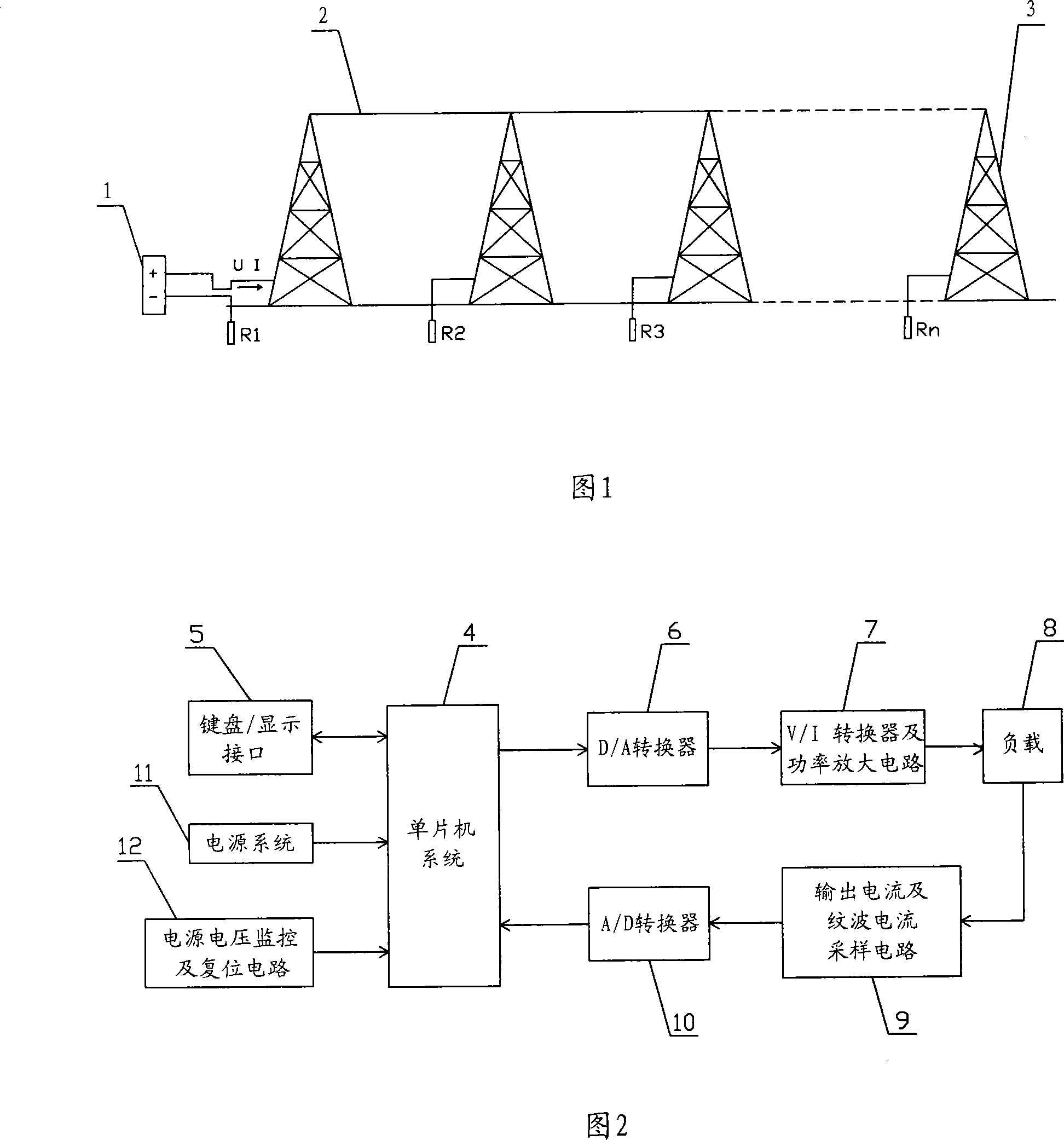
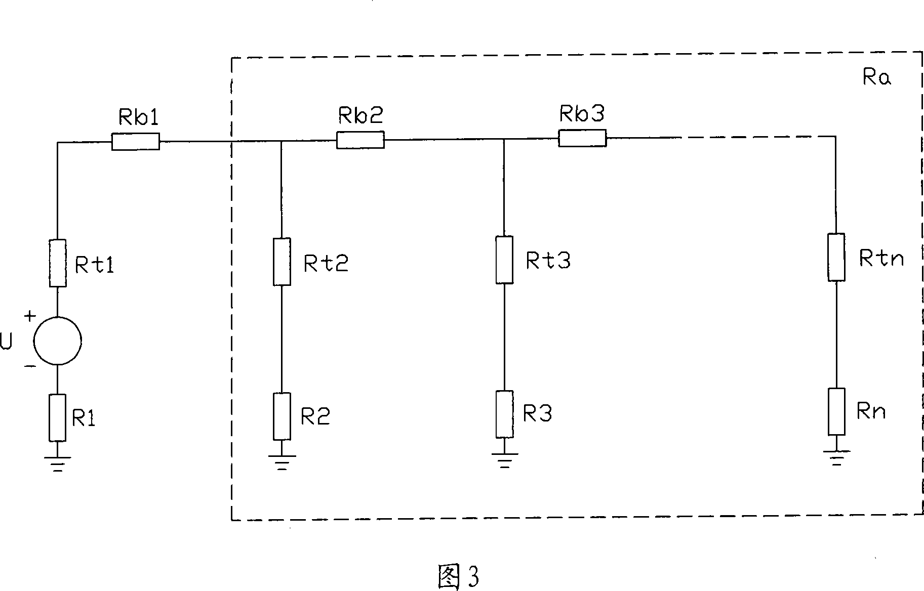
[0021] As shown in Figure 1, each tower 3 in the power transmission line is connected in parallel through the lightning protection wire 2 and the earth. When measuring the grounding resistance, ensure that the lightning protection wire 2 of the tower 3 to be tested is well connected with the tower 3; completely disconnect the body of the tower 3 to be measured Connection with the ground grid; connect the grounding down conductor of the tower 3 to be tested in parallel; connect the tower grounding resistance tester 1 in series between the tower body of the tower 3 and the down conductor, and then reset and measure the instrument. Its corresponding equivalent circuit diagram is shown in Fig. 3 . Tower grounding resistance tester 1 provides output excitation voltage U and loop current I for the entire measurement circuit, R1 is the grounding resistance of the tower to ...


PUM


Abstract

The invention relates to a method for measuring grounding resistance of power transmission tower and a corresponding measurer, which are used for solving the problems present in the prior measurement such as inconvenient line arrangement and measurement interference. The method comprises the following steps of: (1) well connecting a lightning wire with a tower to be measured; (2) completely disconnecting the connection between a tower body of the tower to be measured and a ground net; (3) connecting grounding leads of the tower to be measured in parallel; (4) connecting a tower grounding resistance measuring instrument between the tower body and the leads; (5) resetting the instrument and executing measurement; and (6) reading the measured value. The measurer comprises a singlechip system, a keypad/display interface, a D/A converter, a V/I converter and a power amplifier circuit, an output current and ripple current sampling circuit, an A/D converter, a power supply system and a power voltage monitor and reset circuit. The invention has the advantages of convenient measurement and more accurate measurement by obviating power frequency interference and interference resulting from mutual interference effect in conventional method.

Description

technical field [0001] The invention belongs to the field of high-voltage technology, and in particular relates to a measurement method for the grounding resistance of transmission line poles and towers and a corresponding tester. Background technique [0002] Before the invention of the present invention was proposed, the following two methods were mainly used in engineering for the measurement of the tower resistance of the transmission line: the measurement of the power frequency grounding resistance of the tower generally adopts the three-pole method, that is, the rocker method; for the daily maintenance of the tower and the preventive inspection of the grounding resistance , usually measured by the clamp meter method. [0003] The megger method uses Ohm's law to provide a current loop by setting the voltage pole and current pole, and then measure the grounding resistance value. However, because it needs to lay nearly 100 meters of voltage pole lines and current pole li...

Claims


Application Information

Patent Timeline
Patent Type & Authority Applications(China)
IPC IPC(8): G01R27/20
Inventor 杜忠东谭进刘泽东董晓辉袁明仁余丽娜张学东张敬国唐程
Owner WUHAN NARI LIABILITY OF STATE GRID ELECTRIC POWER RES INST
Why Eureka
Try Eureka