
A split type traffic signal controlling machine system

A signal control machine and traffic signal technology, applied in the field of split traffic signal control machine system, can solve the problems of dazzling signal lights, waste of electric energy, large road damage, etc., to reduce electromagnetic pollution, save line costs, and have high scalability. Effect

Inactive Publication Date: 2008-07-09
QINGDAO HISENSE TRANS TECH
View PDF0 Cites 6 Cited by
  • Summary
  • Abstract
  • Description
  • Claims
  • Application Information

AI Technical Summary

Problems solved by technology

In the prior art, most of them are connected by wire, which leads to a longer route between the traffic signal control machine and the signal lights in each direction, which damages the road more and costs more; and, because the traffic signal control machine By controlling the on and off of the alternating current to control the on and off of the signal lamp, the lead wire between the traffic signal controller and the signal lamp is long, resulting in a large electromagnetic radiation pollution
[0004] In addition, the existing traffic signal controllers cannot adjust the brightness of the signal lights in real time according to the brightness of the ambient light. At night, the brightness of signal lights is rather dazzling, causing discomfort to pedestrians and drivers, and wasting electric energy
[0005] On the other hand, because a crossing in the prior art adopts a centralized control type traffic signal control machine, this traffic signal control machine can only be applicable to the situation that the crossing scale is less than or equal to this crossing after leaving the factory, and for the crossing scale greater than this crossing In other cases, it cannot be used, and the scalability is poor

Method used


Image

  • A split type traffic signal controlling machine system
  • A split type traffic signal controlling machine system

Examples


Embodiment Construction

[0033] The present invention will be described in detail below in conjunction with the accompanying drawings.

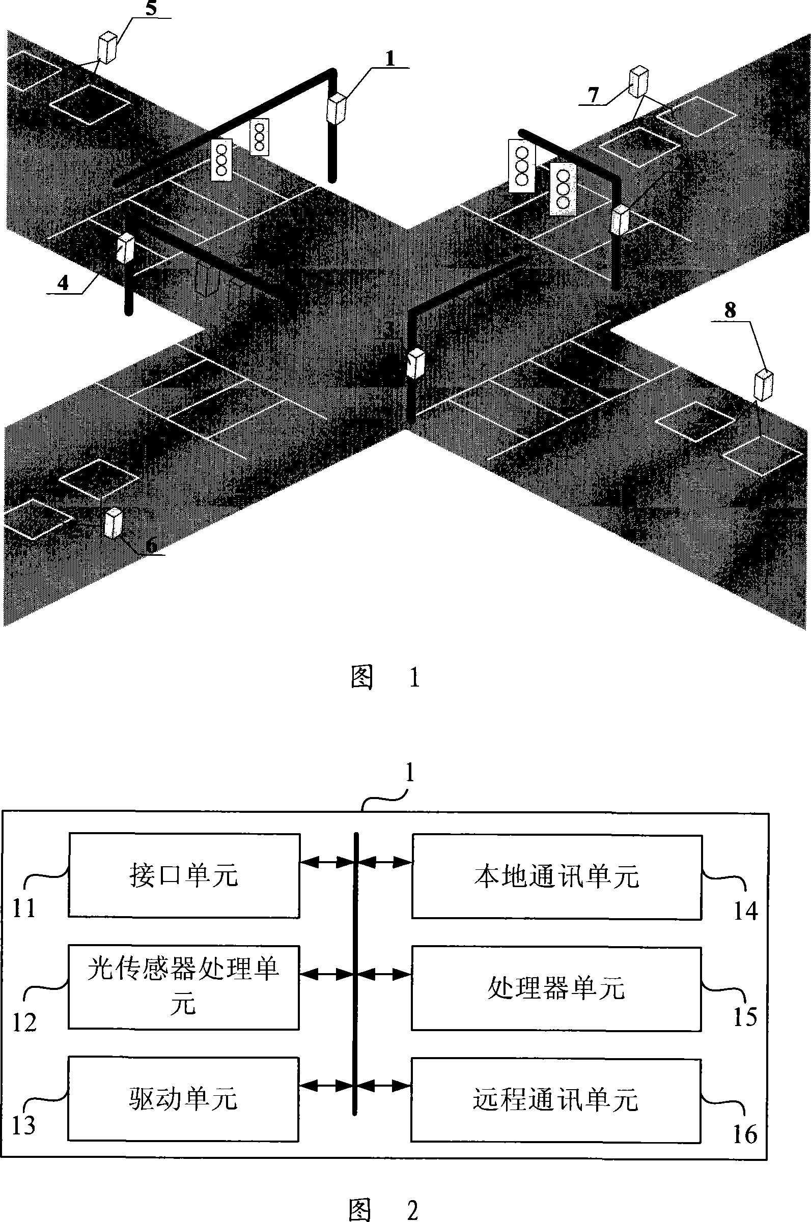
[0034] Referring to FIG. 1 , it shows a schematic diagram of an embodiment of the split traffic signal controller system of the present invention. As shown in the figure, in the present embodiment, the traffic signal control machine system is located in a crossroad, and four traffic signal control machines 1, 2, 3, 4 are set respectively corresponding to the four directions of the crossroad, and the four traffic signal control machines The machines are respectively arranged on the light poles of the control signal lights. In addition, traffic detectors 5, 6, 7, and 8 are respectively provided in the four directions of the intersection to collect traffic data in corresponding directions. The traffic data collected include occupancy rate, queue length, vehicle speed , flow, or just to detect the presence or absence of vehicles, it can be detected by coils buried under...


PUM


Abstract

The invention discloses a split type traffic signal controller system, which is characterized in that the system includes a plurality of signal controllers arranged in different directions of a traffic intersection for performing traffic control in the corresponding directions. Each signal controller has a standard structure so as to be combined based on the traffic intersection scale, thereby improving expandability.

Description

technical field [0001] The invention relates to the field of traffic control, in particular to a split traffic signal controller system. Background technique [0002] In the prior art, the traffic signal control machine system mostly adopts a centralized control type traffic signal control machine at an intersection, and the traffic signal control machine controls the traffic in all directions of the intersection. Therefore, the traffic signal control machine is relatively large in size and takes up too many road resources. [0003] On the other hand, since the centralized traffic signal control machine needs to control the signal lights in all directions of the intersection, it is unavoidable to be connected with each signal light. In the prior art, most of them are connected by wire, which leads to a longer route between the traffic signal control machine and the signal lights in each direction, which damages the road more and costs more; and, because the traffic signal c...

Claims


Application Information

Patent Timeline
IPC IPC(8): G08G1/07
Inventor 陈维强刘新汪志涛孟祥军高力波辛德亮王喆邵辛海管德勇谢清华
Owner QINGDAO HISENSE TRANS TECH
Learn More