
An upper laid sealing and fixture device for spiral lamp and the corresponding sealing techniques

A sealing fixture device and spiral lamp technology, which is applied in the direction of electric tube/light off, etc., can solve the problems of broken glass tube bent feet, reduced product qualification rate, easy to generate stress, etc. Improve product qualification rate and reduce the effect of high temperature heat

Inactive Publication Date: 2008-07-09
周维耀
View PDF0 Cites 9 Cited by
  • Summary
  • Abstract
  • Description
  • Claims
  • Application Information

AI Technical Summary

Problems solved by technology

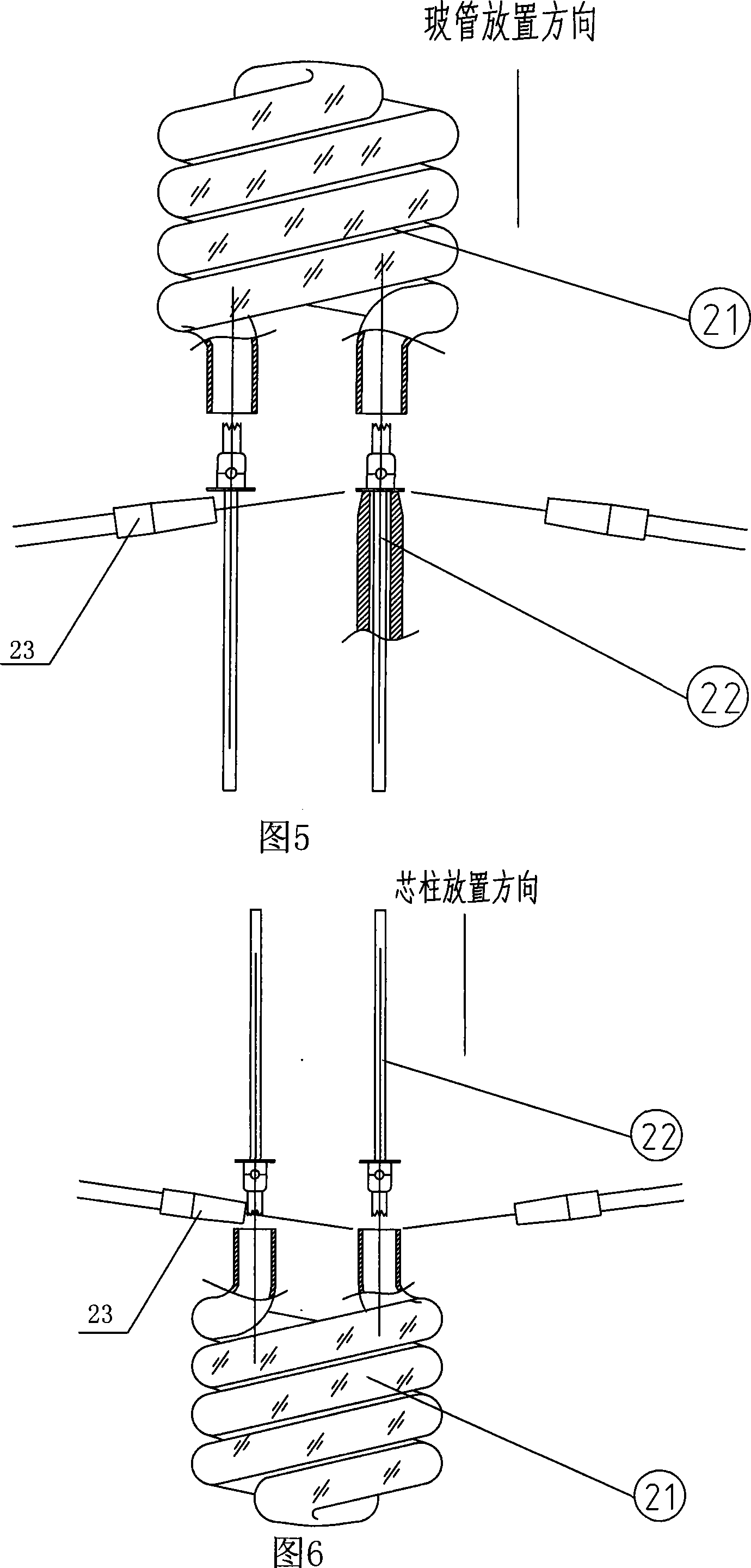
(see accompanying drawing 5), there are many disadvantages in this traditional sealing process: because the tube pin of spiral lamp is too short, it is easy to cause bursting at the bend of the glass tube during sealing, cold burst and uneven thickness of the material at the sealing place, which is easy to generate stress, resulting in When it enters the subsequent process, it bursts or leaks again, and the product qualification rate is greatly reduced
The existing sealing technology in the industry adopts the bottom sealing method. The above-mentioned bursting phenomenon is difficult to eliminate, and the proportion of bursting is very high, and the production cost is increased, which hinders the popularization and promotion of the spiral lamp.

Method used


Image

  • An upper laid sealing and fixture device for spiral lamp and the corresponding sealing techniques
  • An upper laid sealing and fixture device for spiral lamp and the corresponding sealing techniques
  • An upper laid sealing and fixture device for spiral lamp and the corresponding sealing techniques

Examples


Embodiment Construction

[0018] Below the present invention will be further described in conjunction with the embodiment in the accompanying drawing:

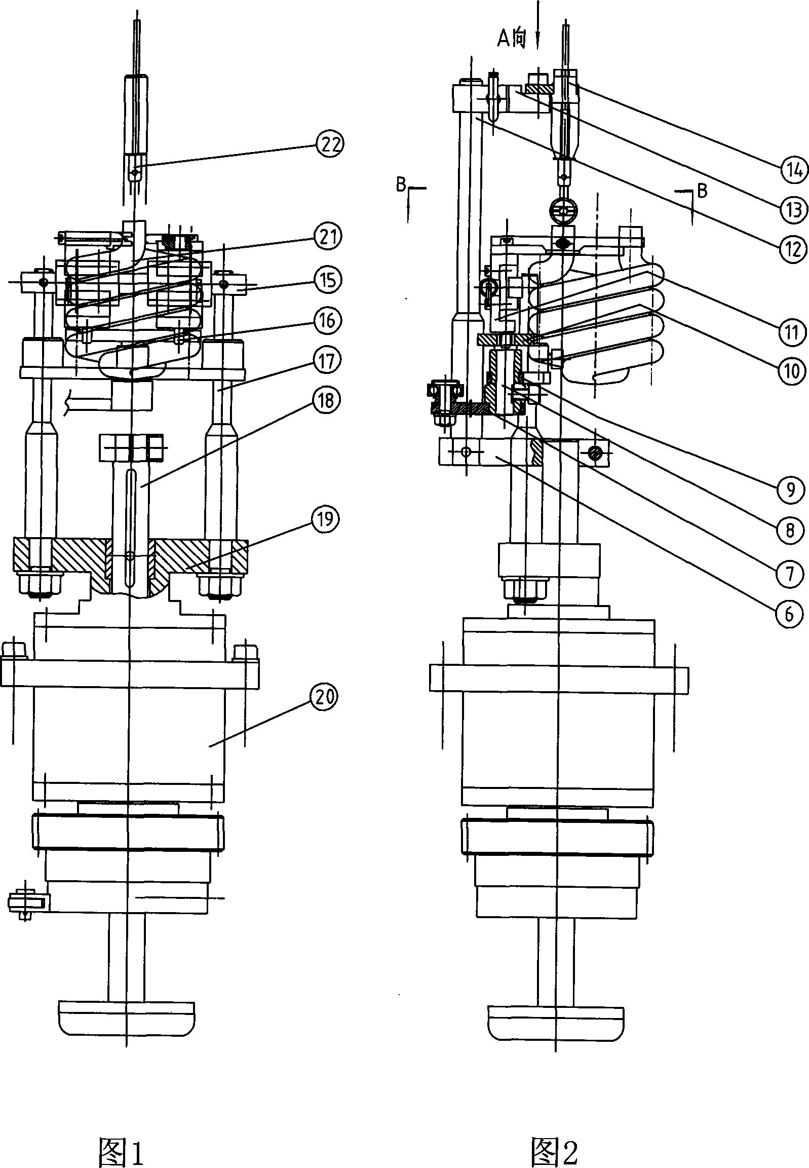
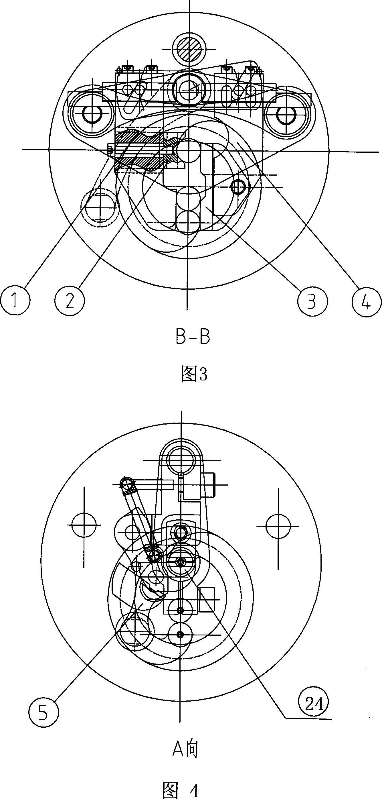
[0019] The sealing clamp device of the present invention consists of a left clamp piece 1, a V-shaped block 2, a movable clamp piece 3, a right clamp piece 4, a rotating arm 5, a connecting block 6, a rotating arm 7, a supporting shaft 8, and an arc support plate 9 , plate-shaped groove cam 10, square block 11, main shaft 12, support block 13, Huff fixed clamp 14, Huff movable clamp 24, slide rail assembly 15, small support shaft 16, two vertical rods 17, connecting lifting shaft 18. Composed of rotating T-shaped shaft 19 and rotating assembly 20.

[0020] The spiral tube of the present invention is clamped and positioned by the left clamp piece 1, the V-shaped block 2 and the movable clamp piece 3 mounted on the right clamp piece 4, and the left clamp piece 1 and the right clamp piece 4 are respectively installed on the slide On the left and right sl...


PUM


Abstract

The invention relates to a spiral lamp top-mounted sealing clamping device and the sealing process, and is characterized in that the invention adopts a movable clamp piece to be arranged on a right clamp piece, a left clamp piece and the right clamp piece are respectively arranged on a sliding track component; a plate-shaped slot cam is arranged on an arc-shaped support plate, a rotating arm is sheathed on a support shaft, the sliding track component is fixed on two vertical poles, the vertical poles are fixed on a rotary T-shaped shaft, a hafu clamp is arranged on the rotating arm, an ascending and descending shaft is linked with a main shaft, and the rotary T-shaped shaft is arranged in a rotary component. A spiral glass lamp tube of the invention is arranged below a sealing fire source, the lamp tube foot is upward; a lamp wire core pole is inserted from the upper part of the spiral glass lamp tube, the spiral glass lamp tube and the lamp wire core pole are fused by flame heating. The clamping of the spiral glass lamp tube is stable and reliable, which can reduce the high temperature heat amount at the tube foot to the maximum extent and fundamentally solve the defects of the traditional sealing mode and the phenomena of cold explosion of the glass tube and the gas leakage which are difficult to overcome.

Description

technical field [0001] The invention relates to an upper-mounted sealing fixture device for a spiral lamp and a sealing process thereof, specifically belonging to the technical field of lamp processing. Background technique [0002] With the continuous progress of human society, energy conservation and environmental protection are highly valued by people. As a new type of energy-saving and environmentally friendly product, my country's compact energy-saving lamp light source has developed rapidly under the active promotion of governments at all levels. Spiral energy-saving lamps are quickly accepted by the market due to their small size, high power, high brightness, and beautiful appearance. The development prospects are broad and the market demand is constantly expanding. It is imminent and urgent to implement the large-scale production of this product with mechanical automation. [0003] The bottom-mounted sealing fixture of the spiral lamp is composed of a glass tube fi...

Claims


Application Information

Patent Timeline
Patent Type & Authority Applications(China)
IPC IPC(8): H01J9/40
Inventor 周维耀
Owner 周维耀
Learn More