A wireless network video monitoring system of high mobility and the corresponding control method

A video surveillance system and wireless network technology, applied in the field of video surveillance instruments, can solve the problems of high rent of wireless network bandwidth, inability to prevent in advance, limited transmission rate, etc., to shorten the construction period of the project, flexible and convenient installation and deployment , cost-effective effect

Inactive Publication Date: 2008-07-09
赵凤济
View PDF0 Cites 17 Cited by
  • Summary
  • Abstract
  • Description
  • Claims
  • Application Information

AI Technical Summary

Problems solved by technology

[0003] However, the current wireless (CDMA / GPRS / EDGE) network video surveillance system is mainly based on the wireless access method of public wireless mobile network communication. Although the mobile public network (CDMA / GPRS / EDGE) covers a long distance, the transmission rate is limited, and the image The effect is poor, and you need to pay high rent for renting the wireless network bandwidth of the mobile public network
WLAN has a high transmission rate but a small coverage area, which is greatly restricted in application.
These real-time monitoring systems are not able to prevent in advance, and use video surveillance data to provide evidence after the event

Method used


Image

  • A wireless network video monitoring system of high mobility and the corresponding control method
  • A wireless network video monitoring system of high mobility and the corresponding control method
  • A wireless network video monitoring system of high mobility and the corresponding control method

Examples


Embodiment Construction

[0072] Please refer to the accompanying drawings for a further description of the present invention.

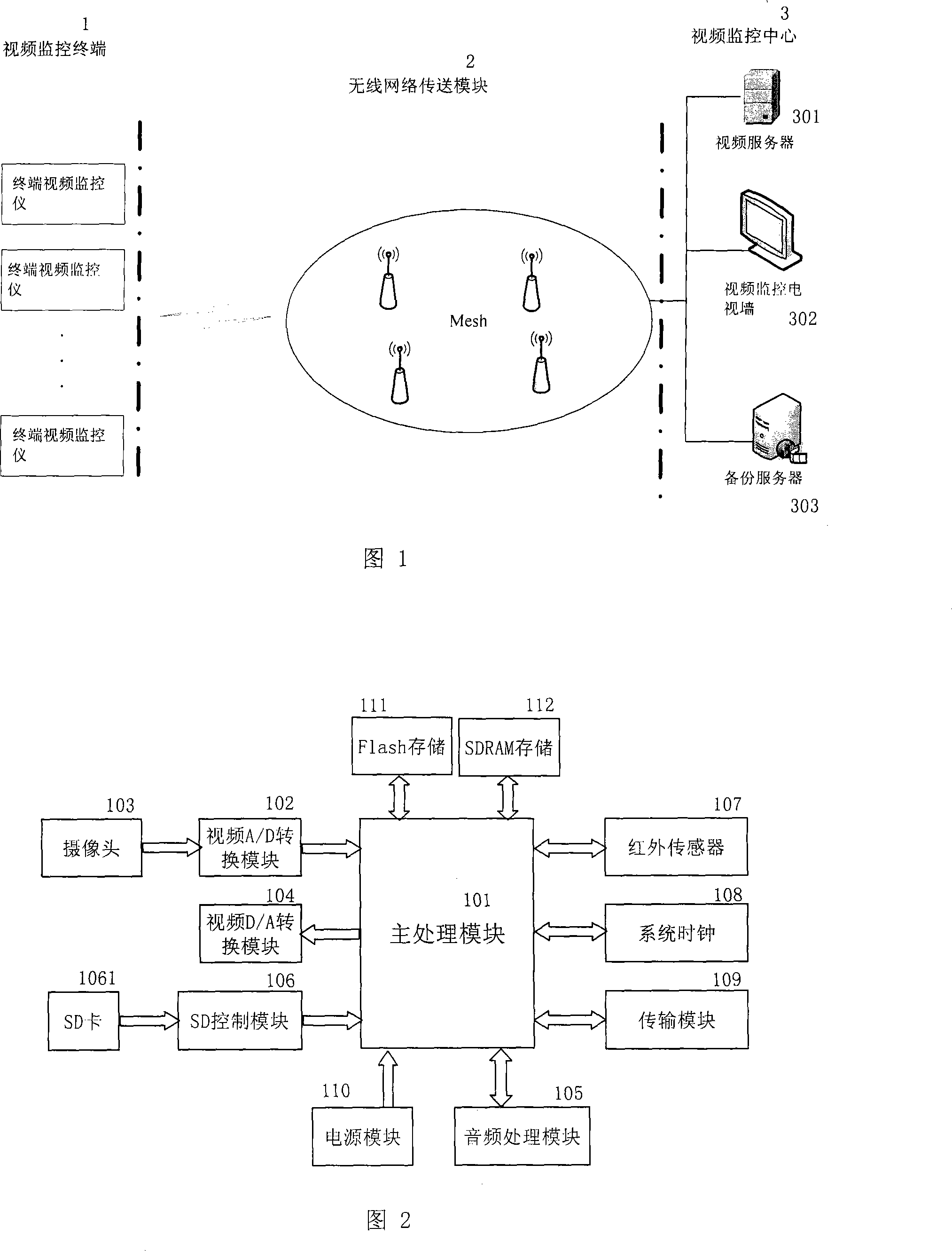
[0073]As shown in Fig. 1 and Fig. 2, the present invention provides a kind of high mobility wireless network video surveillance system, comprises video surveillance terminal 1, wireless network transmission module 2 and video surveillance center 3, and video surveillance terminal 1 collects video by camera 103 The signal is sent to the main processing module 101 after being converted by the A / D conversion module 102, and the output video signal of the main processing module 101 is sent to the video D / A conversion module 104, and the audio input signal is sent to the main processing module after being processed by the audio processing module 105 101, the signal detected by the infrared sensor 107 is input to the main processing module 101, and the main processing module 101 is also connected with the transmission module 109, the system clock 108, and the power supply module 110...


PUM


Abstract

The invention relates to a wireless network video monitoring system with high mobility, which comprises a video monitoring terminal, a wireless network transfer module and a video surveillance system. The video monitoring terminal collects video signals through a camera, then the video signals are sent to a main processing module after being transformed by A/D; voice frequency signals are sent to the main processing module after being processed by a voice frequency processing module, and the video signals and the voice frequency signals processed by the main processing module are stored in a real-time memory card and are sent to the wireless network transfer module, the software of which is controlled by SD. The SD controls the wireless network to automatically be linked to a video server to update the video monitoring video when mobile carriers reach a base station. The invention has the advantages of high reliability, guaranteeing uninterrupted video monitoring, high transmitting speed, low cost of equipment, high price performance, flexibility and practicality; the invention absolutely solves video monitoring blind spots and pitfalls of mobile objects and fills up the video monitoring blank of the mobile objects.

Description

technical field [0001] The present invention relates to a video monitor, in particular to a wireless video monitor connected to a wireless local area network (WLAN) and a control method thereof. The device can coordinate video transmission according to a local storage mode to obtain optimal video monitoring and transmission It is used for wireless video surveillance in mobile fields such as urban public transportation and rail transit systems. In this paper, wireless local area network (WLAN) refers to the wireless local area network using IEEE802.a / b / g protocol, Background technique [0002] As an important security means, video surveillance has a long history of development. Video surveillance system is a high-tech product with high technical content and wide application range. It includes the real-time collection of video signals, compression coding, network transmission, and reception and reconstruction. Due to the development of network technology, the use of network ...

Claims


Application Information

Patent Timeline
Patent Type & Authority Applications(China)
IPC IPC(8): H04N7/18H04L12/28
Inventor 赵凤济
Owner 赵凤济
Why Eureka
Try Eureka