
Rotary drill bit shank, rotary drill bits so equipped, and methods of manufacture

A drill bit and bit body technology, applied in drill bits, manufacturing tools, drilling equipment, etc., can solve problems such as undesired stress, dislocation, etc.

Inactive Publication Date: 2008-07-09
BAKER HUGHES INC
View PDF2 Cites 11 Cited by
  • Summary
  • Abstract
  • Description
  • Claims
  • Application Information

AI Technical Summary

Problems solved by technology

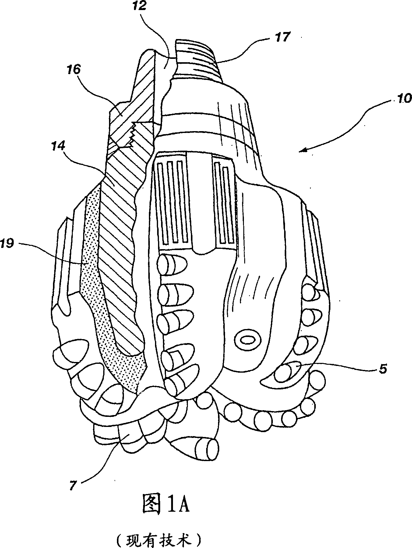
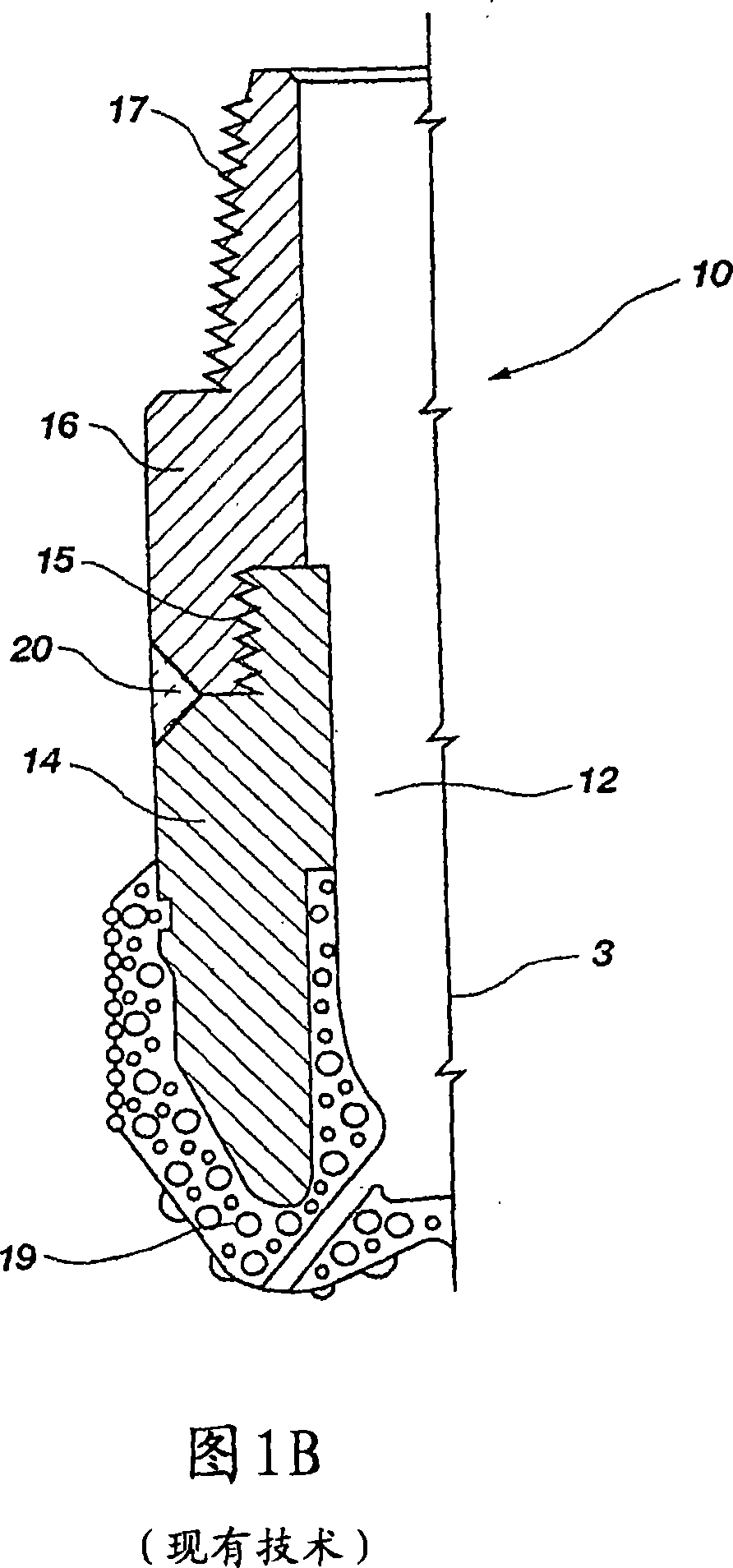
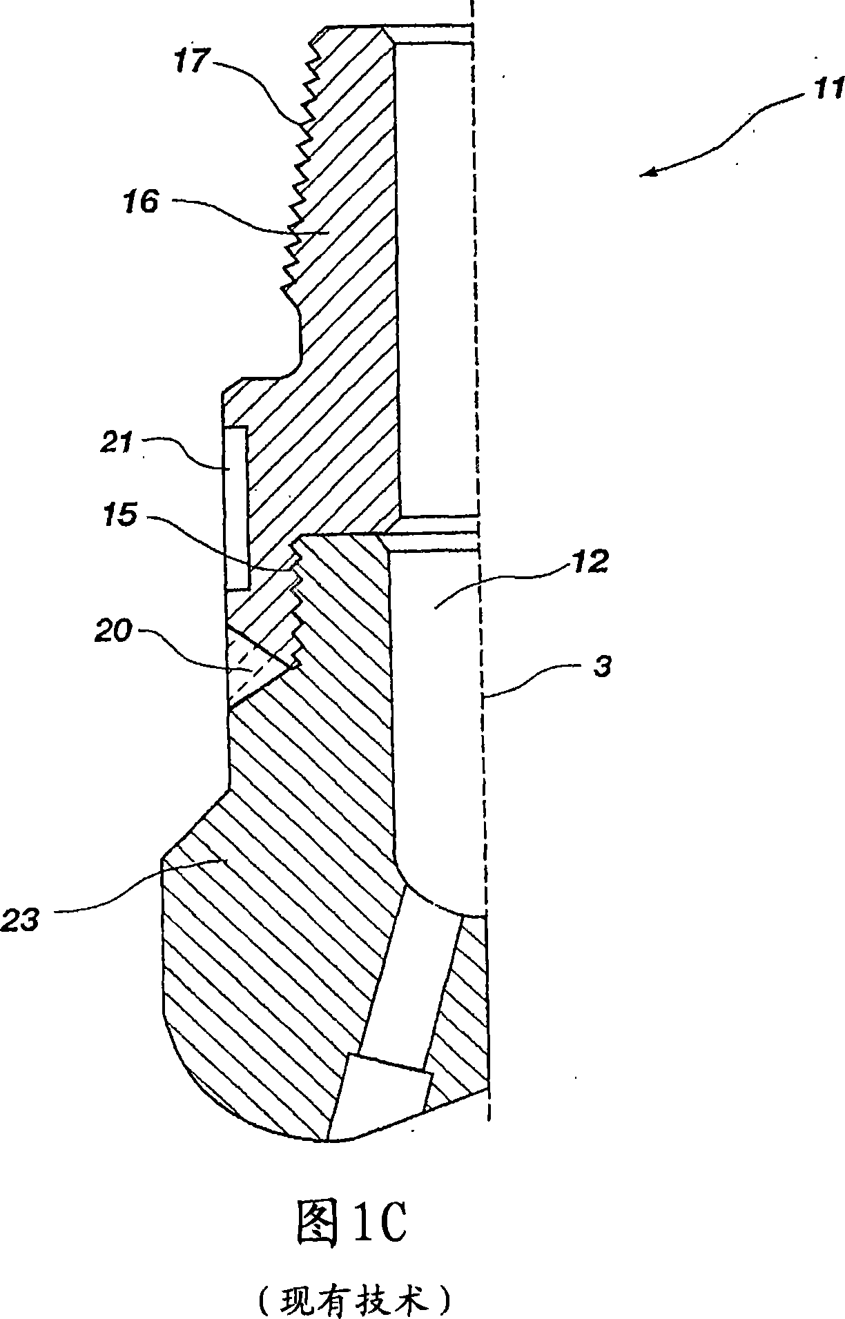
[0013] Here, the inventors observed that a conventional threaded connection between a rod and a blank could create undesirable stresses in the threaded joint and the immediately adjacent welded joint
Additionally, traditional threaded connections can create misalignment between the stem and bit body
In addition, it has been observed that conventional single pass welding between the blank and rod can allow and even promote deformation and misalignment therebetween

Method used


Image

  • Rotary drill bit shank, rotary drill bits so equipped, and methods of manufacture
  • Rotary drill bit shank, rotary drill bits so equipped, and methods of manufacture
  • Rotary drill bit shank, rotary drill bits so equipped, and methods of manufacture

Examples


Embodiment Construction

[0030] FIG. 2A shows a partial cross-sectional view of a matrix type rotary drag bit 110 according to the present invention. Rotary drag bit 110 includes a central longitudinal axis 103 about which holes 112 are generally arranged. Rod 116 may be made of a material having a carbon equivalent of less than about 0.35%, such as, but not limited to, AISI 4130 steel or AISI 4130MOD steel, and may include any known in the art for attachment to a drill string (not shown). The threaded pin connection portion 117 and the drill bit handler surface 121 for fitting onto or removing from the drill string, respectively. Desirably, the rod material has a carbon equivalent weight of even less than about 0.35%, such as less than about 0.30%. One of ordinary skill in the art will recognize that the material selected for rod 116 exhibits at least a minimum yield strength, a minimum ultimate tensile strength, and a minimum impact strength suitable for conditions encountered during drilling with ...


PUM


Abstract

A shank configuration for rotary drill bits is disclosed for positioning of the shank in relation to the bit body. A tapered surface or feature of the shank may be configured and sized to matingly engage a complementarily shaped surface or feature of the drill bit body and thereby become centered or positioned in relation thereto. A deformable element may be disposed between the shank and bit body. Also, the shank may comprise a material having a carbon equivalent of less than about 0.35%. A multi-pass weld procedure may be employed to affix the shank and bit body to one another wherein welds may be formed so that one weld originates at a circumferential position that differs from the origination circumferential position of its immediately preceding weld by at least about 90°. Further, a stress state may be developed within the multi-pass weld. A method of manufacture is also disclosed.

Description

technical field [0001] The present invention generally relates to bit shafts for rotary drill bits for drilling into subterranean formations, and rotary drill bits so equipped. Background technique [0002] A typical rotary drill bit consists of a bit body secured to a hardened steel shank with a threaded pin connection for connecting the bit to the drill string and a crown comprising a surface area bearing for cutting into the drill string. The cutting structure of the formation. Typically, if the drill is a fixed cutting edge or so-called "scraper" drill or drill, the cutting structure comprises a plurality of cutting elements at least partially formed of a superabrasive material, such as polycrystalline diamond. Rotary drag bits using polycrystalline diamond composite (PDC) sheets have been in use for decades. Typically, the bit body may be formed from steel, or a matrix of hard particulate material such as tungsten carbide (WC) infiltrated with a binder, usually a copp...

Claims


Application Information

Patent Timeline
IPC IPC(8): E21B10/54
CPCE21B10/42E21B10/00B23K31/02
Inventor A·F·扎兰德尼克E·C·沙利文R·S·史密斯D·E·鲁夫D·V·罗伯茨A·J·马西
Owner BAKER HUGHES INC
Learn More