Compressor

A technology for a compressor and a compression mechanism, applied in the field of compressors, can solve the problems of increased blade wear, decreased durability, compressor vibration, etc., and achieve the effects of suppressing discharge, improving durability, and reducing vibration and noise.

Inactive Publication Date: 2008-07-16
PANASONIC CORP
View PDF1 Cites 5 Cited by
  • Summary
  • Abstract
  • Description
  • Claims
  • Application Information

AI Technical Summary

Problems solved by technology

Therefore, there are problems that the compressor generates vibration and noise due to the collision between the vane and the cyl

Method used


Image

  • Compressor
  • Compressor
  • Compressor

Examples


Embodiment approach 1

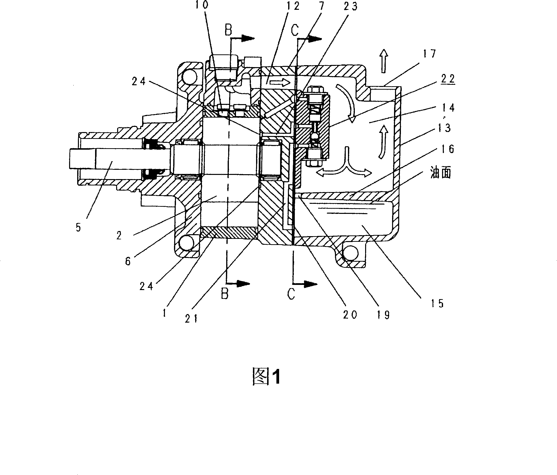
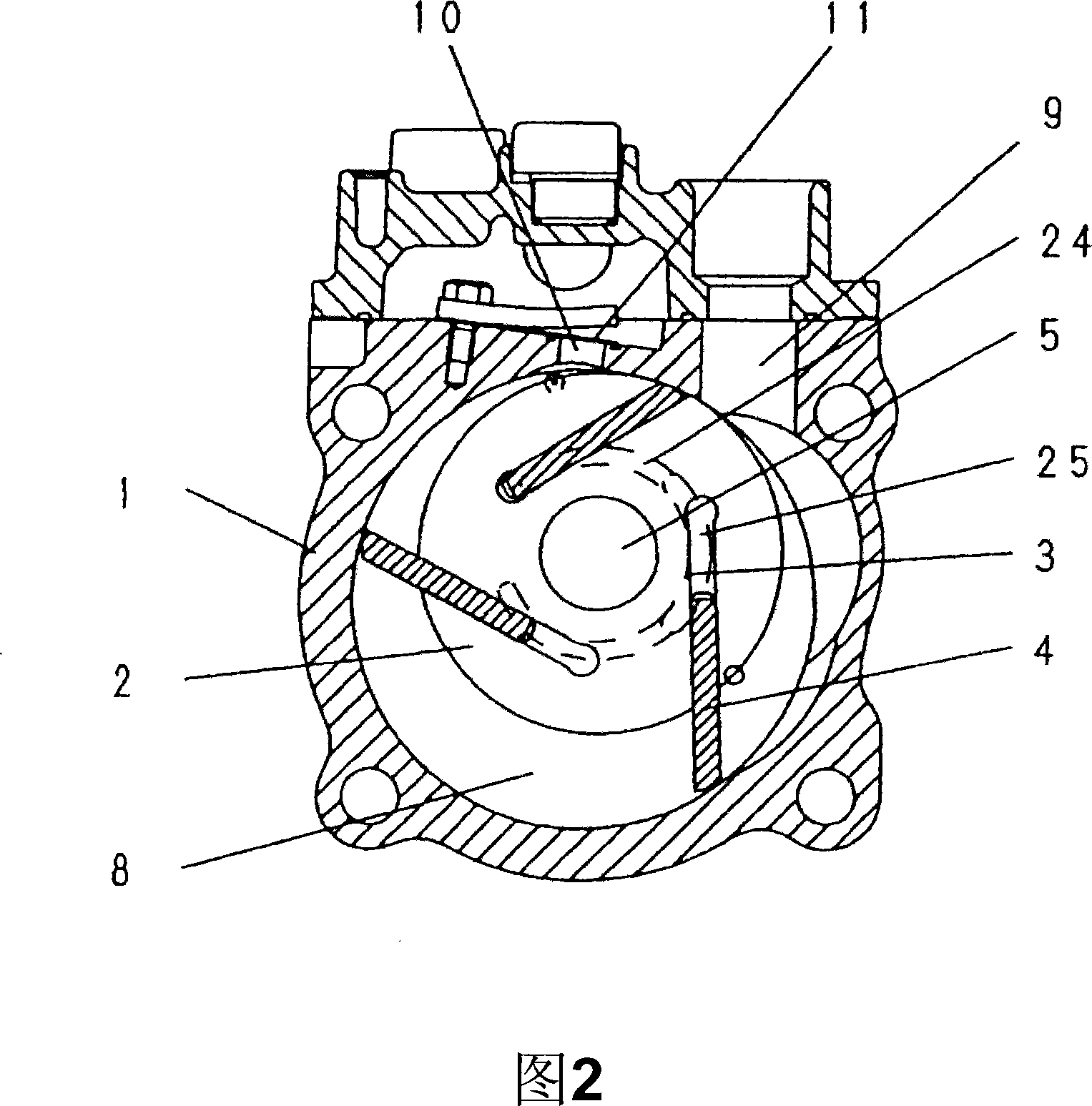
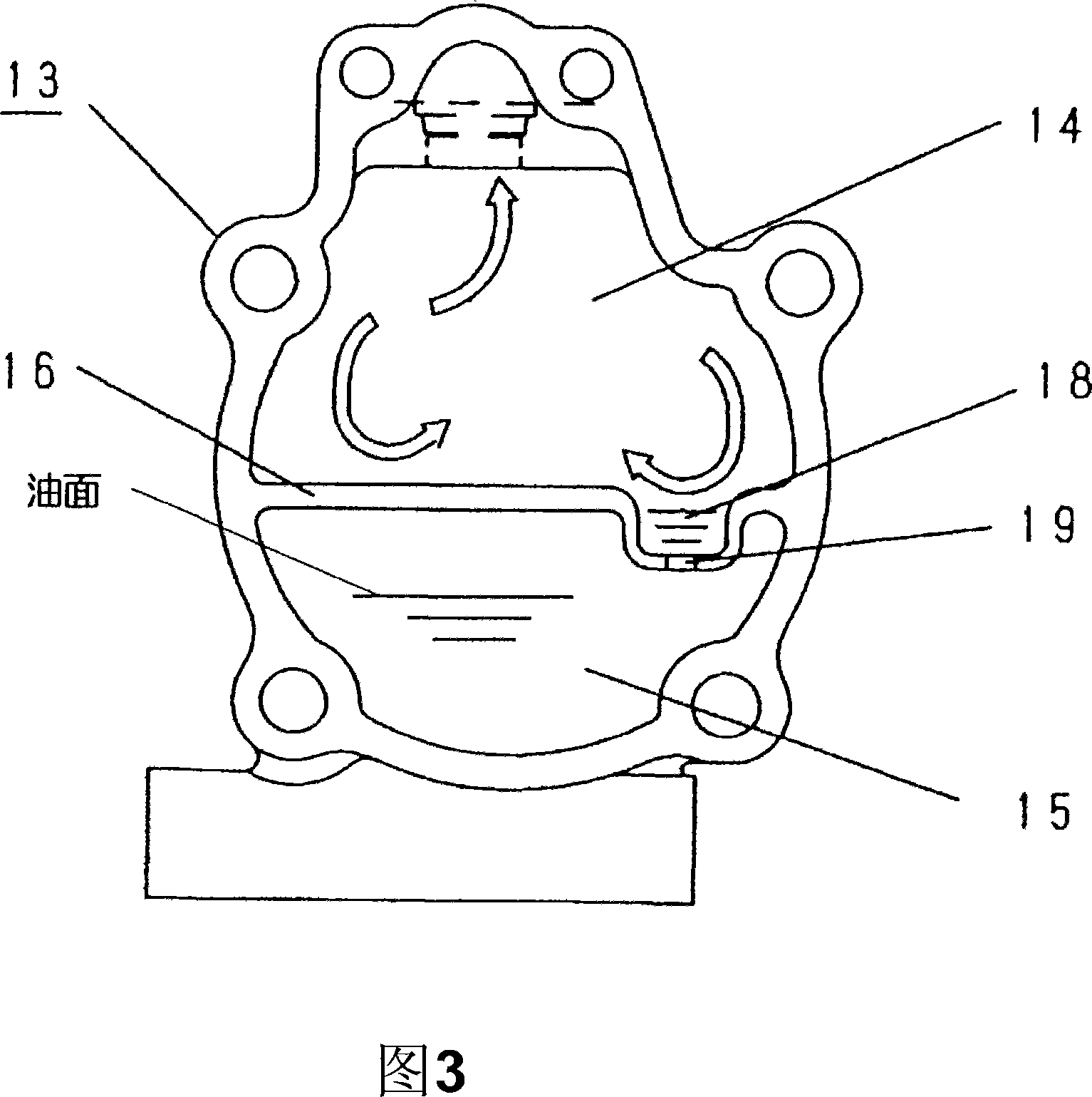
[0056] 1 to 3 show Embodiment 1 of the compressor of the present invention. In addition, although refrigerant|coolant is used and demonstrated in the following embodiment, it may be a compressor which compresses the gaseous fluid other than refrigerant|coolant. As shown in the figure, in this compressor, in a cylinder 1 having a cylindrical inner wall, a substantially cylindrical rotor 2 is accommodated with a part of its outer circumference forming a slight gap with the inner wall of the cylinder 1, and is freely rotatable. .

[0057] A plurality of vane slots (slots) 3 are provided at equal intervals on the rotor 2 , and vanes 4 that can slide freely are respectively inserted into the vane slots 3 . The rotor 2 is rotated by rotational drive of a drive shaft 5 integrally formed therewith.

[0058] Openings at both ends of the cylinder 1 are closed by a front side plate 6 and a rear side plate 7 , and a working chamber 8 is formed inside the cylinder 1 . The working chambe...

Embodiment approach 2

[0068] Next, another embodiment of the compressor of the present invention will be described with reference to FIG. 4 . In addition, the same reference numerals are assigned to components substantially the same as those in the above-mentioned embodiment, and description thereof will be omitted, and only differences will be described.

[0069] In the compressor of the present embodiment, a part of the partition wall 16 is an inclined surface, and the inclined surface forms a concave portion protruding toward the oil storage chamber 15 as the oil accumulation portion 18 . A first straightening plate 26 b is provided at a position facing the inclined surface in the high pressure chamber 14 . By arranging the front end of the first straightening plate 26b to face the inclined surface, the main flow of the refrigerant does not flow into the oil reservoir 18 . In addition, a second straightening plate 26 a other than the first straightening plate 26 b is provided in the high-pressu...

Embodiment approach 3

[0072] Next, other embodiments of the compressor of the present invention will be described with reference to FIGS. 5 and 6 . In addition, the same reference numerals are assigned to components substantially the same as those in the above-mentioned embodiment, and description thereof will be omitted, and only differences will be described.

[0073] In the compressor of the present embodiment, the area of ​​the communication passage 19 is such that lubricating oil separated from the refrigerant is discharged to the oil storage chamber 15 without being accumulated in the oil reservoir 18 .

[0074] In this embodiment, it is preferable that the size and passage area of ​​the communication passage 19 be an appropriate size selected according to the viscosity of the lubricating oil used. Specifically, the width of the communication passage 19 is 1 cm, the depth is 3 cm, and the passage area is 3 cm. 2 .

[0075] By adopting the above method, during operation, since the amount of l...


PUM


Abstract

In order to improve the noise of the compressor, improve the durability and improve the system performance, prevent fluctuations and foaming of the lubricating oil stored in the oil storage chamber caused by the gas fluid discharged into the high-pressure chamber, suppress the reduction of the oil storage volume, and suppress the Evacuation of lubricating oil in the refrigeration cycle. The compressor of the present invention has a high-pressure chamber and an oil storage chamber formed by dividing and forming a rear side plate and a partition wall in a high-pressure box, and an oil accumulation part formed by a part of the partition wall being recessed is provided, and the oil accumulation part is provided with a The lubricating oil separated from the fluid slides to the communication path that is discharged from the oil storage chamber. A rectifying plate is arranged on the upper part of the oil accumulation part so that the main flow of the air fluid does not flow into the oil accumulation part, and the communication path is that the lubricating oil separated from the air fluid does not Therefore, even if a large amount of refrigerant is discharged at start-up, it is possible to prevent fluctuations and foaming of the lubricating oil, suppress the reduction of the oil storage amount, and suppress the flow of refrigerant to the oil storage chamber. Evacuation of lubricating oil in the refrigeration cycle.

Description

technical field [0001] The present invention relates to a compressor used in an automobile air conditioner and the like. Background technique [0002] A mechanism for separating lubricating oil from the compressed refrigerant and an oil storage part for storing the separated lubricating oil are provided in the high-pressure chamber of the existing compressor, and the vane back pressure applying device is used during driving. The lubricating oil stored in the oil storage part is supplied to the blade back pressure part to press and push the blade from the rotor, and performs lubrication of the cylinder, the blade, the rotor, and the like. [0003] In such a compressor, fluctuations in the oil level of the oil reservoir must be suppressed, and the oil level of the lubricating oil stored in the oil reservoir must be kept at least higher than the lubricating oil supply port at the lower part of the blade back pressure applying device. Therefore, a substantially horizontal stabi...

Claims


Application Information

Patent Timeline
IPC IPC(8): F04C29/02F04B39/02F04C18/344
Inventor 山本信之
Owner PANASONIC CORP
Why Eureka
Try Eureka