
Engine vibration isolation system based on combined suspension and its control method

An engine and vibration isolation technology, applied in motor-driven engines, non-rotational vibration suppression, power units, etc., to achieve the effects of improving durability and riding comfort, cost-effectiveness and practicability

Inactive Publication Date: 2008-07-16
CHONGQING UNIV
View PDF0 Cites 52 Cited by
  • Summary
  • Abstract
  • Description
  • Claims
  • Application Information

AI Technical Summary

Problems solved by technology

The second is to solve the problem that the dynamic process of engine vibration isolation is uncertain, and it is difficult for the engine to obtain satisfactory vibration isolation effect in a wide frequency range with a single control strategy. A semi-active control that does not depend on the precise model and includes two control strategies is adopted. The method is to change the damping force of the combined suspension system according to the vibration excitation frequency of the engine, the force on the base and the motion state of the damper, and suppress the transmission of the vibration energy of the engine to the carrier body while reducing the vibration of the engine itself, so that the engine can operate in a wide frequency range. Effective vibration isolation within the range

Method used


Image

  • Engine vibration isolation system based on combined suspension and its control method
  • Engine vibration isolation system based on combined suspension and its control method
  • Engine vibration isolation system based on combined suspension and its control method

Examples


Embodiment Construction

[0018] The implementation of the present invention will be described in detail below in conjunction with the accompanying drawings and specific embodiments.

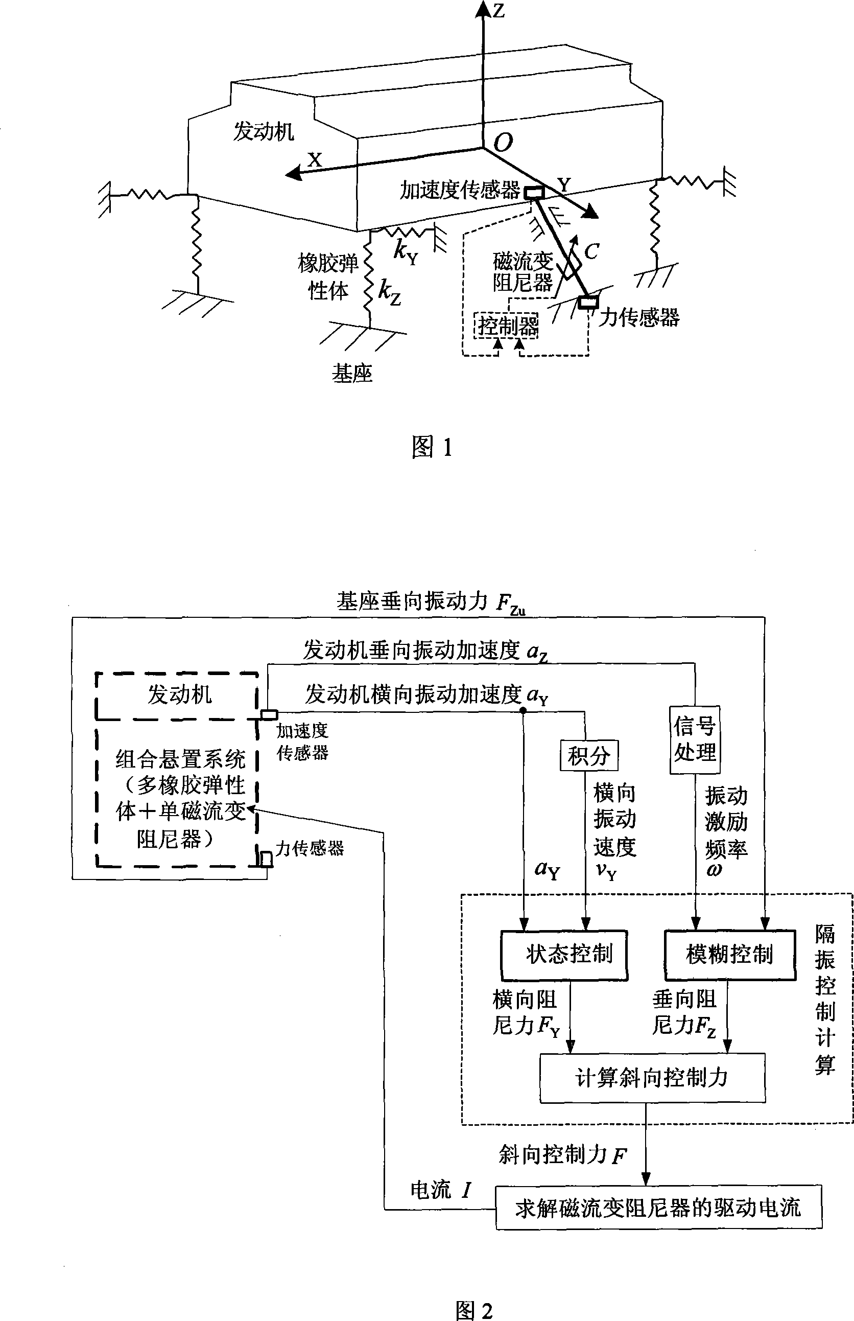
[0019] As shown in Figure 1, the engine vibration isolation system based on the combined suspension of rubber elastic body and magneto-rheological damper constructed by the present invention is shown.

[0020] Due to the limitation of external connection conditions such as transmission devices, the forced vibration of the complete engine is mainly manifested as vertical motion, followed by lateral vibration. In the figure, the origin O represents the position of the center of mass of the engine, the X-axis is parallel to the crankshaft of the engine, the Y-axis is perpendicular to the X-axis and parallel to the base plane, and the Z-axis is determined according to the right-hand rule and is perpendicular to the base plane. K Z Indicates the vertical stiffness of the rubber elastic body, K Y Represents the transverse st...


PUM


Abstract

The invention provides an engine vibration isolation system which is based on a combination suspension and a control method, relating to the automatic control technical field. The invention forms the combination suspension by a plurality of passive rubber elastomers and a single controllable magneto-rheological damper which is obliquely arranged between the middle part of the engine and a base; an acceleration sensor and a force sensor respectively extract the vertical and transverse vibration acceleration of the engine body and the vertical vibration force of the base, so as to calculate the vibration excitation frequency and the transverse vibration speed of the engine; an engine vertical vibration isolation fuzzy control rule and a transverse damping state control rule are established in a controller, and an oblique control force of the magneto-rheological damper is calculated; the driving current of the magneto-rheological damper is determined by an oblique control force, the damping force of the combination suspension is adjusted in real-time, the transmission of the vibration energy of the engine is restricted. The invention can lead to effective vibration isolation of the engine in wide-frequency range, reduces the self vibration of the engine, and improves the durability and the riding comfort of a carrier.

Description

technical field [0001] The invention relates to the field of automatic control, in particular to an engine vibration isolation method based on a combined mount. Background technique [0002] The engine is the main source of vibration on vehicles such as vehicles and ships. The suspension system that can isolate vibration in a wide frequency range can effectively reduce the transmission of engine vibration energy and improve the durability and ride comfort of the vehicle. [0003] At present, the engine generally adopts the passive suspension vibration isolation system made of rubber elastic body, which has a simple structure and low cost. It has a good vibration isolation effect in the low frequency range, but the damping is too small; the rubber will be dynamically hardened at high frequencies. , the dynamic stiffness is significantly increased, while the damping is almost unchanged, which cannot meet the performance requirements of the engine for vibration isolation and no...

Claims


Application Information

Patent Timeline
IPC IPC(8): F16F15/02B60K5/12B63H21/12
Inventor 李锐陈伟民廖昌荣张红辉余淼刘会兵
Owner CHONGQING UNIV
Learn More