Air valve and air sealing body with the same

A technology of air sealing body and air stop valve, which is applied in the direction of preventing mechanical damage, control valve, valve device, etc. It can solve the problem of poor cushioning effect of gas packaging bag A10, increased production process and manufacturing cost, and poor inflation effect. It can reduce the production process, simplify the structure, and facilitate the production.

Active Publication Date: 2008-07-16
KUNSHAN AIRBAG PACKING CORP
View PDF4 Cites 14 Cited by
  • Summary
  • Abstract
  • Description
  • Claims
  • Application Information

AI Technical Summary

Problems solved by technology

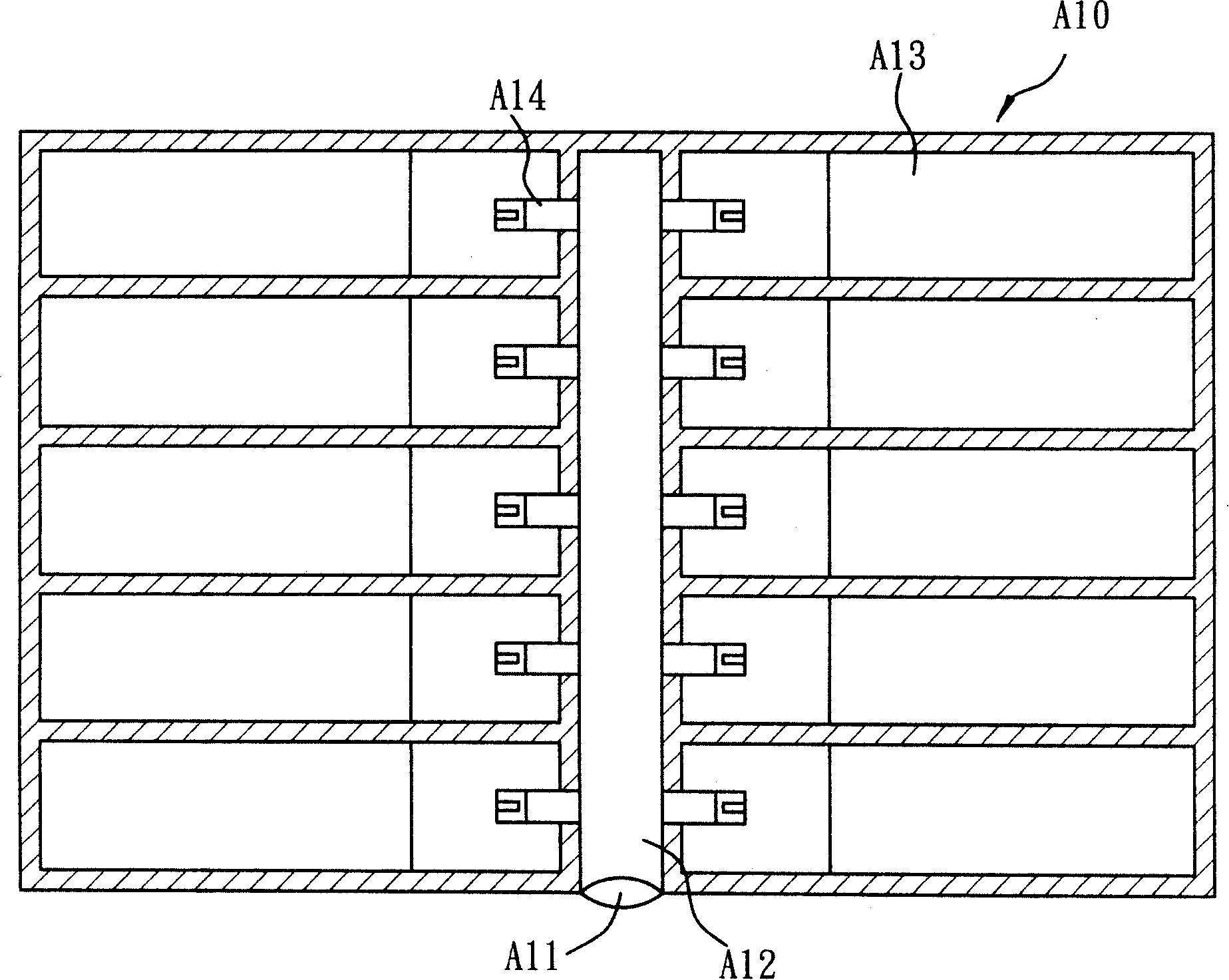
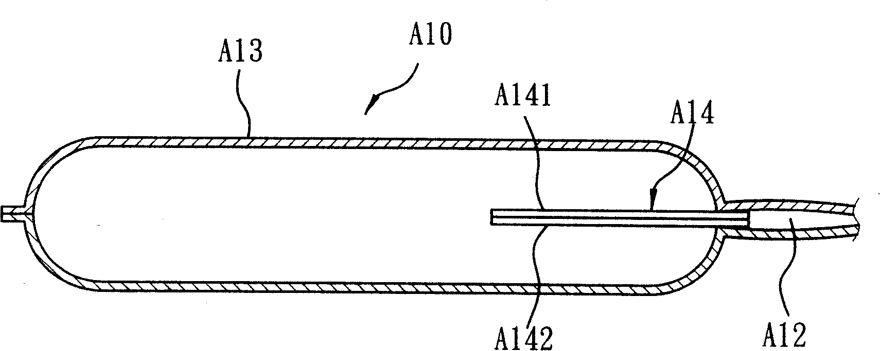
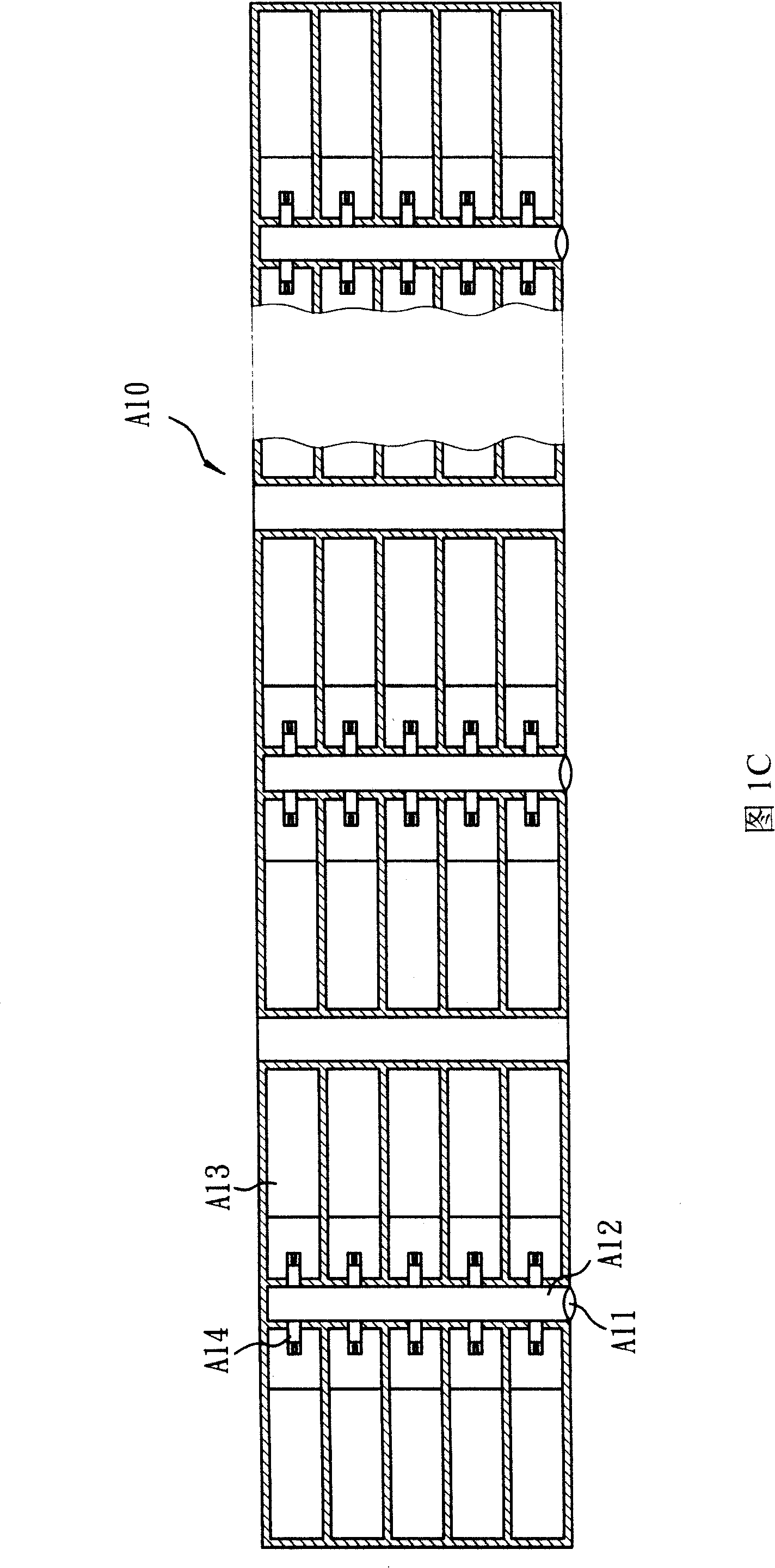
However, this gas packaging bag A10 needs to be equipped with multiple air valves A14 to inflate multiple air chambers A13, and the setting of multiple air valves A14 will greatly increase the production process and manufacturing cost
Furthermore, the above-mentioned structure will make the air chamber A13 close to the air inlet A11 inflated first, and the air chamber A13 far away from the air inlet A11 will inflate slowly or have a poor inflation effect, resulting in poor cushioning effect of the inflated gas packaging bag A10 good

Method used


Image

  • Air valve and air sealing body with the same
  • Air valve and air sealing body with the same
  • Air valve and air sealing body with the same

Examples


Embodiment 1

[0044] figure 2 , image 3 , Figure 4A and Figure 4B Shown is Example 1 of the present invention. in figure 2 The shown air stop valve of the present invention includes: two inner membranes 1a and 1b, a heat-resistant material 1c, an air inlet 2e, an air channel 5, and a cut hole 8.

[0045] The two inner membranes 1a and 1b are stacked up and down, and heat-resistant material 1c is coated inside. The heat-resistant material 1c starts from the top of the inner membrane and extends downward for a certain length. Glue or ink, so that the heat-resistant material 1c is bonded on the two inner films 1a or 1b by heat sealing. The shape of the heat-resistant material is elongated, oval or T-shaped with a wide top and a narrow bottom.

[0046] The peripheries of the four sides of the inner film 1a and 1b are bonded in a heat-sealing manner to form heat-sealing lines 3a, 3b, 3c, and 3d, wherein the heat-sealing lines 3a, 3b, and 3c are completely closed heat-sealing lines, an...

Embodiment 2

[0055] Such as Figure 5 Shown, the stop valve of present embodiment 2 and embodiment 1 (see figure 2 ) is that the gas channel 5 of the present embodiment 2 is longer and includes a plurality of bronchial channels 6, and the incision hole 8 is located at the end of the bronchial channel, so the bronchial channel 6 is used to connect the gas channel 5 and the incision hole 8. The bronchi are formed by bonding the two inner membranes by heat sealing.

[0056] When inflated, the two inner membranes 1a and 1b of the stop valve are pulled apart, thereby opening the air inlet 2e, allowing external air to enter the gas channel 5 through the air inlet 2e, and along the gas channel 5, and its respective The air passages 6 and the cut holes 8 flow into the air chamber 40 of the air-tight body to inflate the air chamber 40 .

Embodiment 3

[0058] Such as Figure 6 As shown, the difference between this embodiment 3 and the above-mentioned embodiment 1 is that the gas stop valve of this embodiment 3 includes a plurality of gas channels 5 uniformly arranged in the transverse direction, and the upper end of each gas channel 5 is connected to the gas inlet 2e A plurality of cut holes 8 are arranged on the side of each gas channel 5 .

[0059] The heat-sealing line 3d does not completely bond the peripheral edges of the two inner membranes, and the place with the heat-resistant material 1c is not bonded, and the place without the heat-resistant material 1c is bonded.


PUM


Abstract

The invention provides an air valve and an air sealing body provided with the air valve. The air valve comprises two internal films which are superposed up and down, at least one air inlet, at least one gas passage and at least one cutting opening; the air inlet is formed at the position which is not completely bonded at the circumference of one edge of the two internal films; the circumferences of the rest three edges of the internal films are bonded; one end of the gas passage is connected with the air inlet and formed between the two internal films; the cutting opening is arranged on the internal film beside the air passage. The air sealing body of the invention comprises two external films which are superposed up and down and at least one sealing air chamber which is formed by the external films; the air valve is arranged on the air chamber. The invention can prevent the leakage of the gas in the air chamber after inflation, and realizes extremely fine air-lock effect; furthermore, all air chambers can be inflated at the same time; the air sealing body with the air valve of the invention has the advantages of simple structure, convenient manufacture, and reducing production operation flow and manufacture cost.

Description

technical field [0001] The invention relates to a gas stop valve and an air sealing body with the gas stop valve, in particular to a hole-cut type gas stop valve and an air seal body with the hole-cut type gas stop valve. Background technique [0002] In the prior art, the method used to cushion the packaged items is to protrude a plurality of small airbags on a plastic sheet, and wrap the plastic film on the outer periphery of the article to achieve shock absorption and buffering effect, but the shock absorption capacity of the small airbags is limited. For larger vibration or impact loads, the effect of cushioning and shock absorption cannot be achieved, so there is a gas packaging bag made of resin film. [0003] see Figure 1A To Fig. 1C, gas packaging bag A10 is provided with air inlet A11, is connected with air inlet A11 and is provided with air inlet A12, and a plurality of air chambers A13 are connected respectively on both sides of air inlet A12, each air chamber A1...

Claims


Application Information

Patent Timeline
Patent Type & Authority Applications(China)
IPC IPC(8): F16K15/20B65D81/03B65D30/24
Inventor 廖建华廖耀鑫简伯欣
Owner KUNSHAN AIRBAG PACKING CORP
Why Eureka
Try Eureka