
Power supply circuit of clock

A technology of power supply circuit and clock circuit, which is applied in the direction of power supply circuit, battery circuit device, circuit device, etc., and can solve the problem that the capacitance power supply circuit can not adjust the voltage and limit the discharge curve of the capacitor, the discharge current of the clock discharge circuit is small, and affect the volume and cost of the capacitor and other issues, to achieve the effect of being conducive to commercial promotion and application, prolonging the power supply time, and low cost

Active Publication Date: 2010-05-26
VERTIV CORP
View PDF2 Cites 0 Cited by
  • Summary
  • Abstract
  • Description
  • Claims
  • Application Information

AI Technical Summary

Problems solved by technology

[0004] 1. The time to maintain power supply is directly related to the capacitor capacity. Since the capacitor capacity used first is large, increasing the capacitor capacity will directly affect the volume and cost of the capacitor
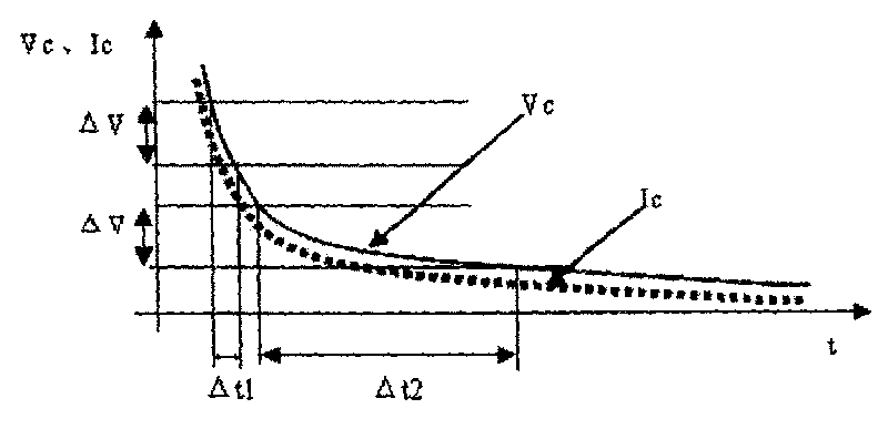
[0005] 2. The capacitor discharge curve is an exponential type, and the energy utilization rate is low
[0006] 3. A current-limiting resistor can be connected in series between the power supply circuit and the clock circuit, but since the type of discharge curve remains unchanged, and there is voltage division of the resistor, the lower limit of the capacitor discharge voltage is increased, so the series-connected current-limiting resistor can only be slightly extended. Discharge time, limited effect
[0007] 4. Since the discharge current of the clock discharge circuit is extremely small, the minimum is hundreds of nanoamperes, it is impossible to adjust the voltage and current limit of the capacitor power supply circuit to change the type of capacitor discharge curve, because the power consumption of the voltage regulator chip or the reference source itself is huge The power consumption of the clock circuit

Method used


Image

  • Power supply circuit of clock
  • Power supply circuit of clock
  • Power supply circuit of clock

Examples


specific Embodiment approach 1

[0041] like Figure 4 As shown, a clock power supply circuit includes an energy storage circuit, a control circuit and a current limiting module. The energy storage circuit includes a supercapacitor C1 for storing energy. The control circuit includes a first diode D1 and a second diode D2, the anode of the first diode D1 is connected to the anode of the power supply Vcc, the cathode of the first diode D1 is connected to the anode of the supercapacitor C1, The anode of the second diode D2 is connected to the anode of the power supply Vcc, and the cathode of the second diode D2 is connected to the first input terminal B of the clock circuit. The negative pole of the supercapacitor C1 is connected to the second input terminal A of the clock circuit. When the power supply Vcc is normally powered, both the first diode D1 and the second diode D2 are turned on, the power supply Vcc normally supplies power to the clock circuit, and charges the supercapacitor C1 of the energy storage...

specific Embodiment approach 2

[0046] like Figure 7 As shown, the difference between this embodiment and the first embodiment is that the third resistor R3 is not arranged between the collector of the second transistor Q2 and the positive power supply terminal of the energy storage circuit, but is arranged between the second transistor Q2 Between the emitter and the first input terminal B of the clock circuit.

specific Embodiment approach 3

[0047] like Figure 8 As shown, the difference between this specific embodiment and the first specific embodiment is that the third resistor R3 is omitted, that is, the collector of the second transistor Q2 is directly connected to the positive power supply terminal of the energy storage circuit.


PUM


Abstract

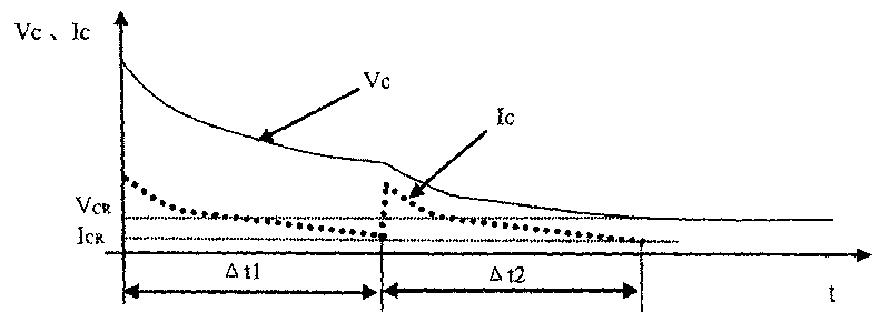
The invention discloses a clock power supply circuit which comprises an energy storage circuit, a control circuit and a current limiting module, wherein the control circuit is connected between a power source and the energy storage circuit; under the control of the control circuit, the energy storage circuit can store energy when the power source provides power supply and completes discharge for the clock circuit when the power source stops power supply; the current limiting module is connected between the energy storage circuit and the clock circuit; moreover, the current limiting module ensures step by step discharging of the energy storage circuit and also ensures that the clock circuit works under low current conditions. The invention, which can prolong power supply time and lowers therequirements on the energy storage circuit, greatly reduces the capacity requirements of a super capacitor; moreover, that the invention can reduces the size of the super capacitor is convenient forthe miniaturization of a digital circuit.

Description

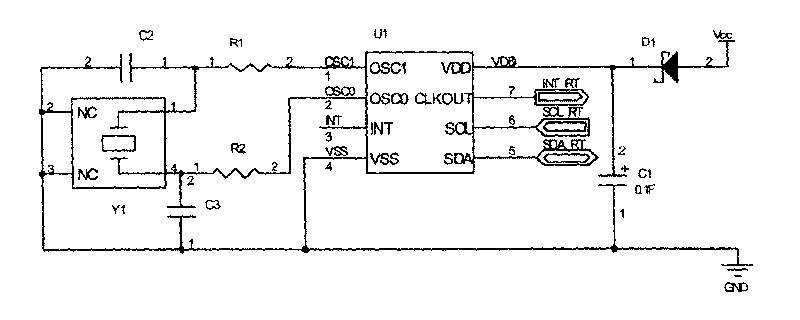
technical field [0001] The invention relates to a power supply circuit, in particular to a clock power supply circuit. Background technique [0002] Existing clock power supply circuits are generally divided into two types: battery-powered and supercapacitor-powered. The application of battery-powered clock power supply circuits is limited due to the impact of battery charging times, life, and high and low temperature environments. At present, clock power supply circuits using supercapacitors are widely used. like figure 1 As shown in the existing clock circuit, its power supply is composed of a diode D1 and a supercapacitor C1, and the capacity of the supercapacitor C1 is 0.1F. The supercapacitor in the present invention refers to a large-capacity capacitor with a capacity of tens of thousands of microfarads. When the input power supply VCC is powered off, the clock chip U1 and the crystal oscillator Y1 still need to continue to work to maintain the clock count, and thei...

Claims


Application Information

Patent Timeline
Patent Type & Authority Patents(China)
IPC IPC(8): G04C10/00G04G19/00G04G19/06H02J7/00
Inventor 吴连日
Owner VERTIV CORP
Learn More