Control circuit

A technology of control circuit and current control circuit, which is applied in the field of control circuit, can solve the problems of inability to display dimming effect and reduce the efficiency of dimming circuit, etc.

Inactive Publication Date: 2008-07-16
BEYOND INNOVATION TECH
View PDF0 Cites 32 Cited by
  • Summary
  • Abstract
  • Description
  • Claims
  • Application Information

AI Technical Summary

Problems solved by technology

For example, due to the charging and discharging characteristics of the capacitor, the current signal output to the LED will have a rising slope and a falling slope, so even when the switch is turned off by the control signal, the remaining charge in the cap...

Method used


Image

  • Control circuit
  • Control circuit
  • Control circuit

Examples


Embodiment Construction

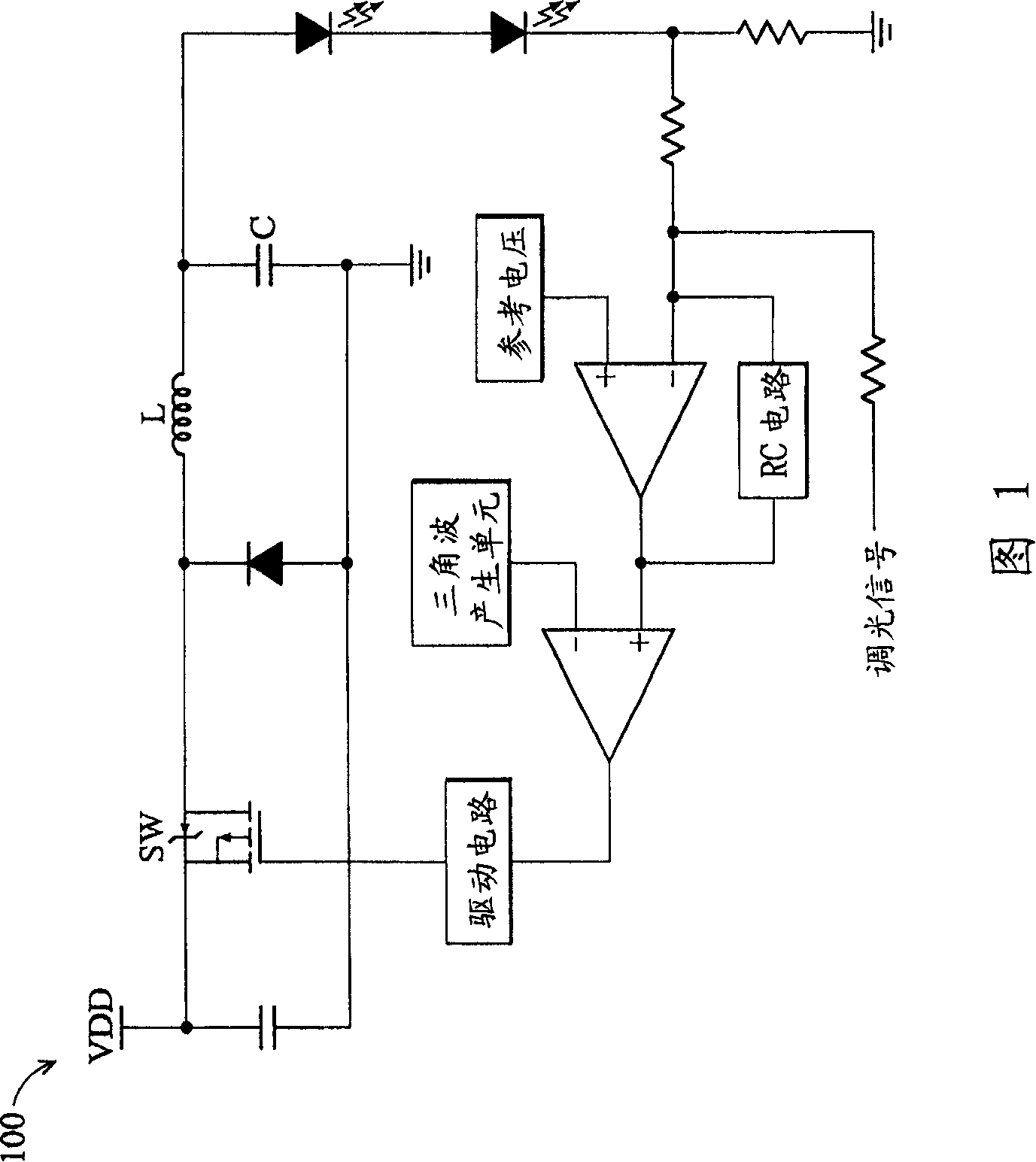
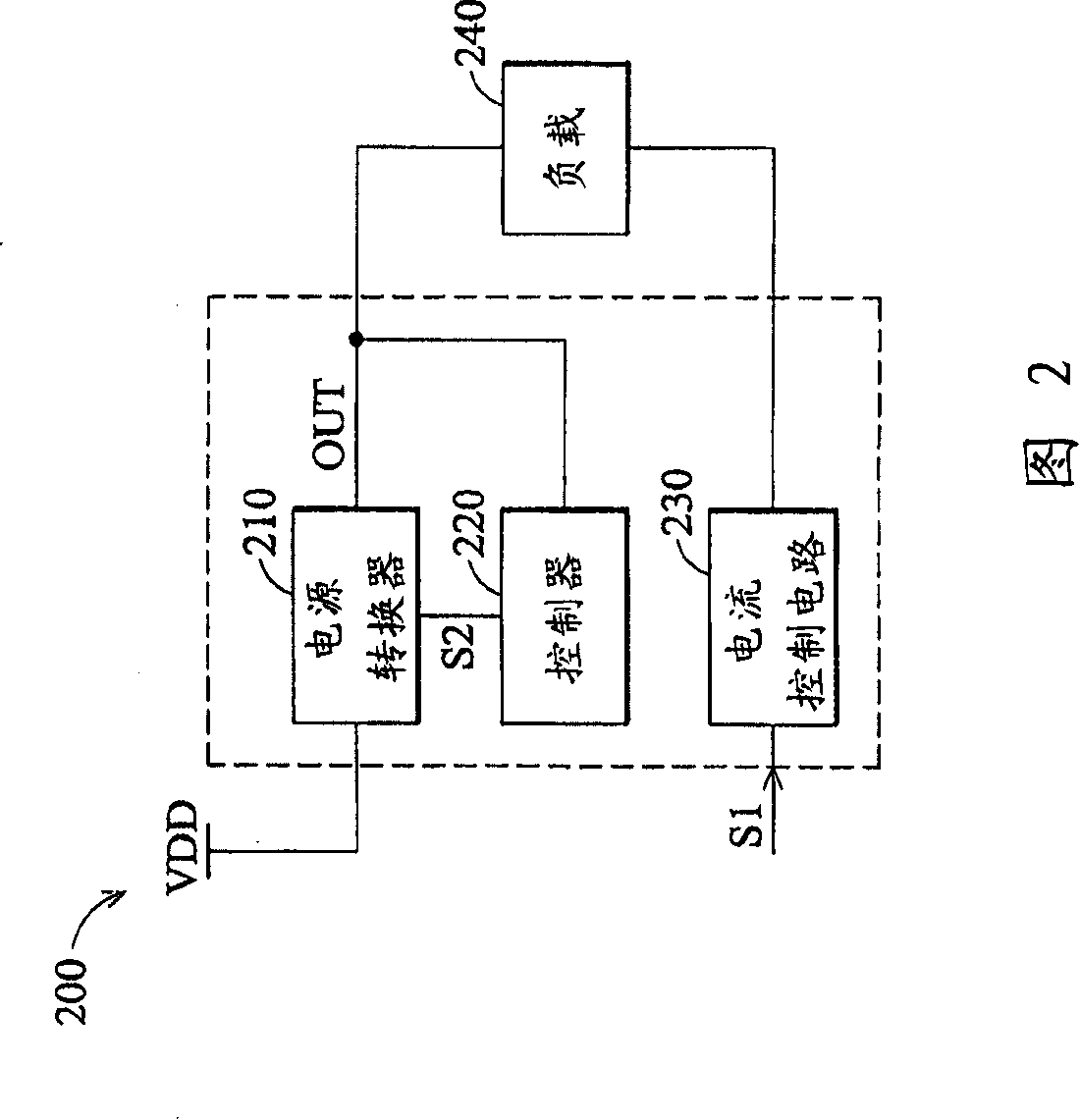
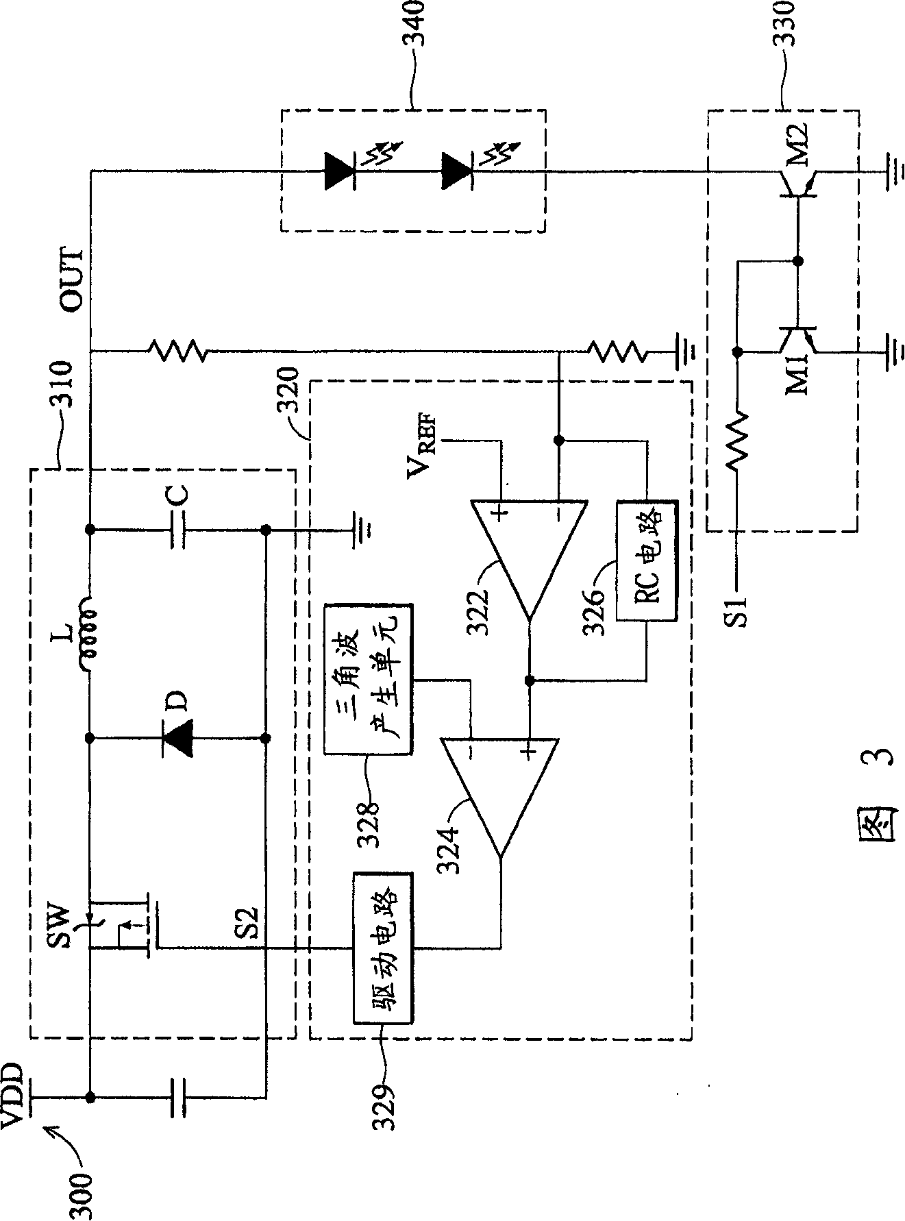
[0028] The present invention is a control circuit for controlling the supply current of a load such as a light-emitting diode, and receiving a dimming signal so that the current flowing through the load can be changed immediately with the change of the dimming signal without causing time lag Delay to achieve better dimming effect. To achieve this purpose, the present invention uses the voltage of the feedback (feedback) load as the main feedback signal to maintain the stability of the supply voltage, and the dimming signal is directly input to a current control circuit composed of a current mirror circuit to directly The purpose of dimming is achieved by controlling the current flowing through the load, and the current controlled by the current control circuit will not be fed back to the circuit including the aforementioned delay elements (such as switching elements, capacitors, etc.). According to the present invention, since the dimming signal does not pass through the afore...


PUM


Abstract

The invention provides a control circuit for controlling the current running through a load, comprising a power converter, a controller and a current control circuit. According to a control signal, the power converter converts a first voltage signal into a second voltage signal. Coupled with power converter, the controller adjusts the control signal in respond to the second voltage signal to make the second voltage signal maintain in a desired value. Coupled with the load, the current control circuit controls the current running through the load in respond to a dimming signal.

Description

technical field [0001] The invention relates to a control circuit, in particular to a control circuit of a light emitting diode. Background technique [0002] The dimming circuit is widely used in the brightness control of various display devices such as liquid crystal display panels or light-emitting diodes. It is a common control circuit that uses an external dimming signal to control the current or voltage flowing through the load to produce different brightness. A common light-emitting diode control circuit is to provide a fixed current to determine the brightness of the light-emitting diode. This type of control circuit usually includes a power converter, a controller and a current detection circuit, wherein the power converter includes at least a switching element, a diode, an inductor and an output capacitor, and the controller includes at least A resistor-capacitor (RC) circuit consisting of a capacitor. The controller generates a control signal, and adjusts the c...

Claims


Application Information

Patent Timeline
IPC IPC(8): H05B33/08H05B44/00
Inventor 王家伟黄世中
Owner BEYOND INNOVATION TECH
Why Eureka
Try Eureka