Inertia friction welding machine

A friction welding machine, inertial technology, applied in welding equipment, welding equipment, non-electric welding equipment and other directions, can solve the problems of radial deformation of pipe fittings, inability to accurately position circular welding parts, and inability to meet the requirements, and achieves increased moving distance, The effect of reducing the difficulty of clamping and the risk of welding

Inactive Publication Date: 2008-07-23
NO 59 RES INST OF CHINA ORDNANCE IND
View PDF0 Cites 30 Cited by
  • Summary
  • Abstract
  • Description
  • Claims
  • Application Information

AI Technical Summary

Problems solved by technology

Since the oil cylinder and the transmission spindle are integrated in this structure, the oil cylinder is small and the piston moving distance is short, so it cannot realize the pressure adjustment of large flow during the rotation process; when it cannot meet the radial friction welding of large-diameter workpieces, the tooling clamping part radial The need for moving distance
[0007] 3) The special tooling device is clamped by the Mohs taper and is always in a free state. It cannot accurately position the annular weldment at any position in the tooling device, and it is easy to cause radial deformation of the pipe fittings; and the special tooling device needs to bear a large Axial force, complex structure, time-consuming and labor-intensive loading and unloading
[0008] 4) Radial inertial friction welding is carried out on the axial inertial friction welding machine. The radial pressure clamped on the annular weldment is implemented by the main thrust oil cylinder. When the main thrust oil cylinder pushes the special tooling device, the sliding table also follows Move forward, so there is a certain space at the rear end where the special tooling device is connected to the main shaft at the end of the moving fixture. During the welding process, the ends of the cylindrical and round pipe weldments are in a cantilever state, and the clamping torque of the rotating fixture cannot overcome the welding time. Influenced by welding torque, it is easy to cause surface strain of clamped cylindrical and circular tubular weldments

Method used


Image

  • Inertia friction welding machine
  • Inertia friction welding machine
  • Inertia friction welding machine

Examples


Embodiment

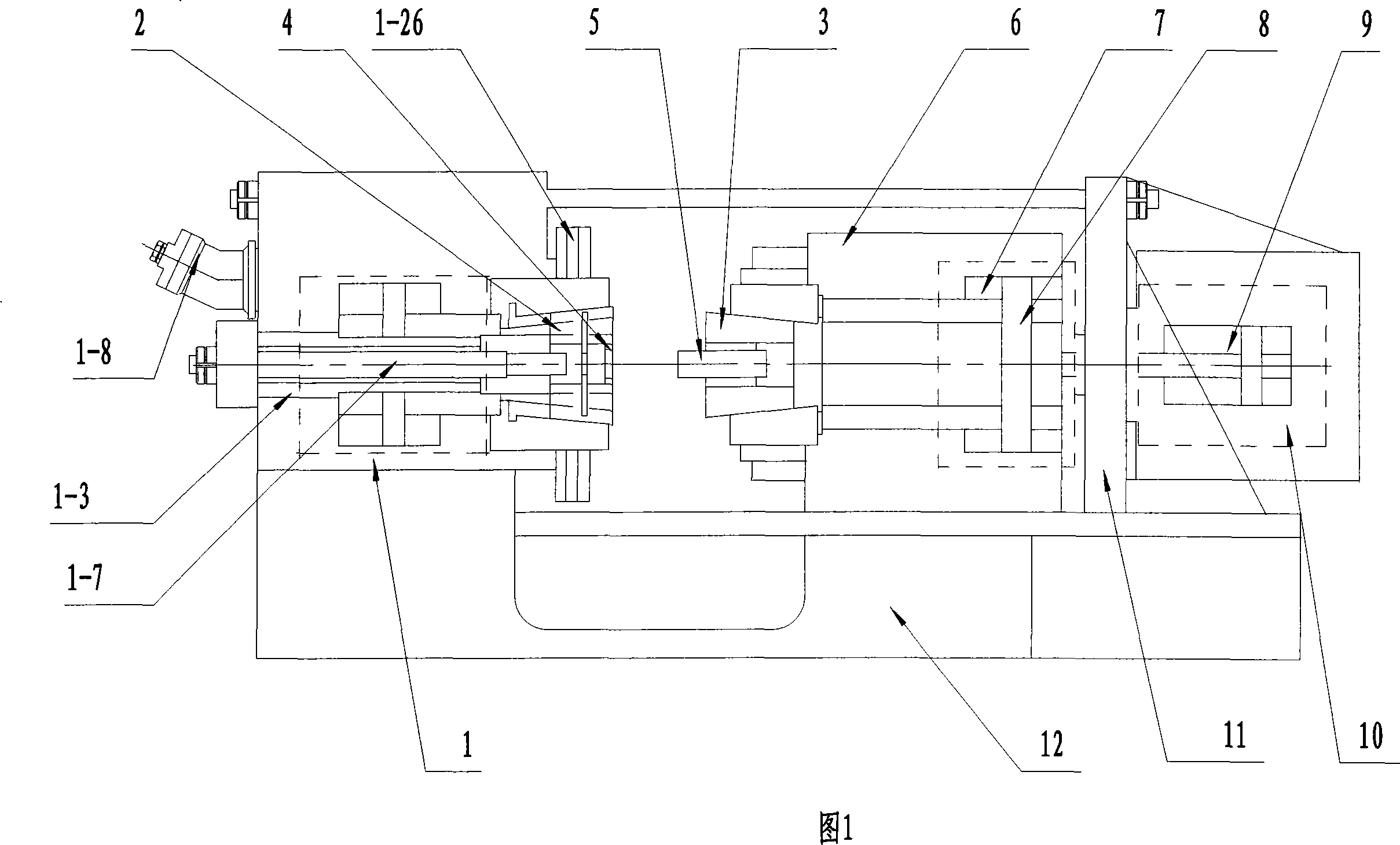
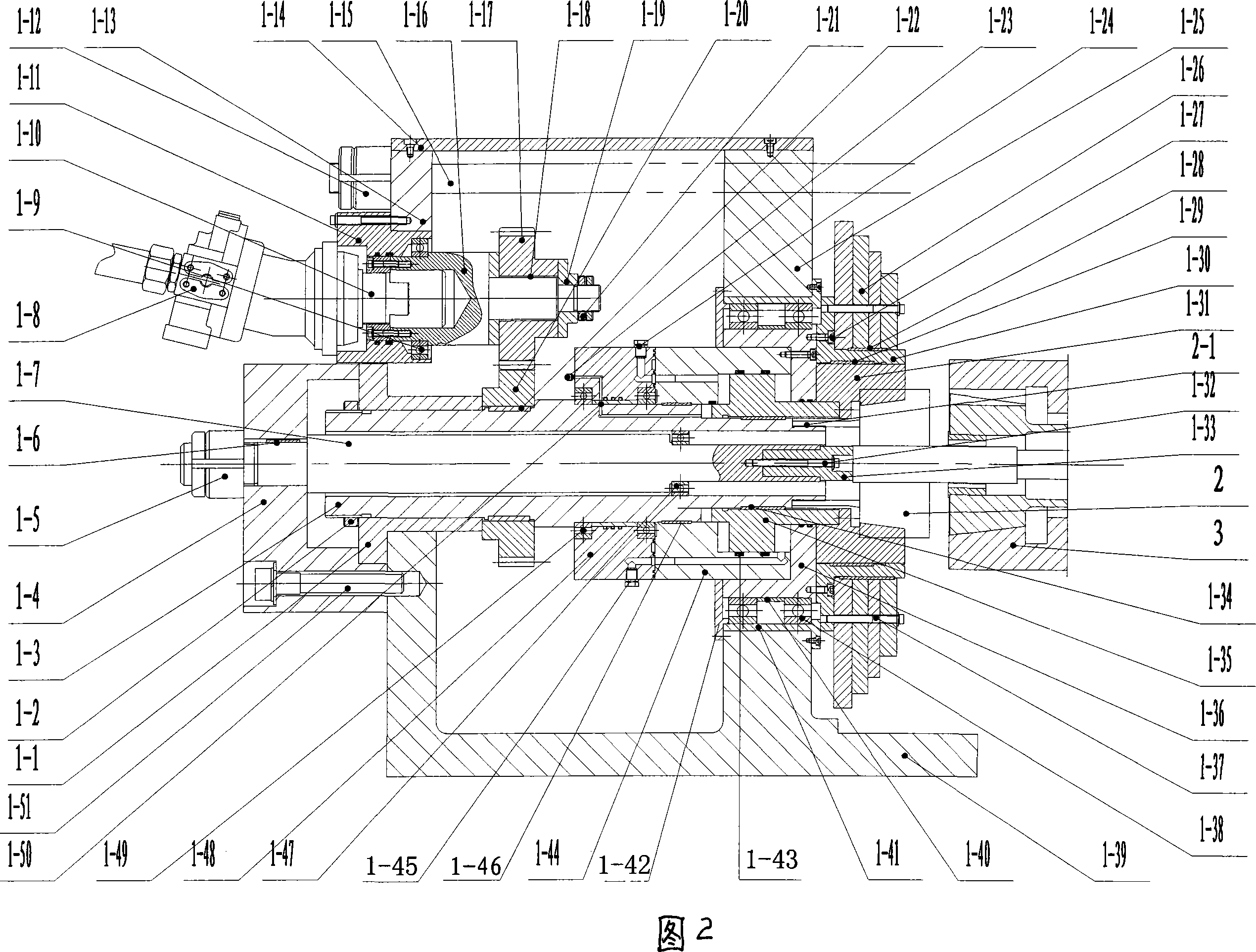
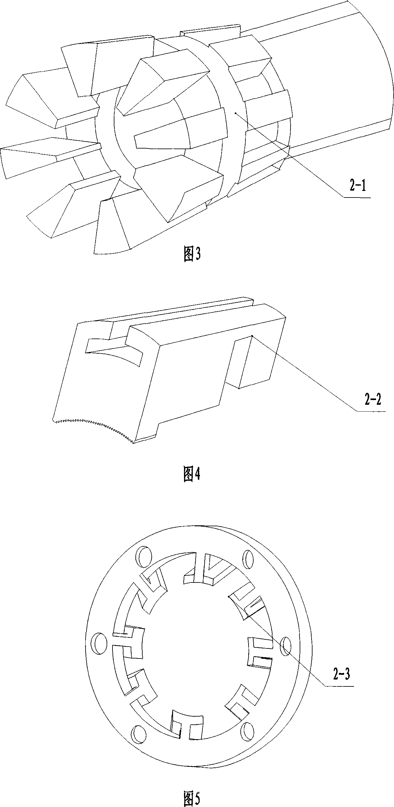
[0025] Embodiment: Referring to Figures 1 to 5, an inertia friction welding machine includes a base 12, a slide table 6 on the slideway of the base 12, a moving fixture 3 connected to the inside of the slide table 6, a moving fixture cylinder 7 and a moving fixture Piston 8, the support 11 that is connected on the outside of slide table 6 and the auxiliary stabilizing thrust oil cylinder 9 of auxiliary stabilizing pressurization system 10, and the support 1-39 and left support 1-13 that are connected at the inner end of the slideway on the base 12 1. The spindle box 1 formed by connecting the right bracket 1-25, the cover plate 1-14 of the spindle box 1 passes through the hole on the left bracket 1-13, the right bracket 1-25 and the upper part of the bracket 11, and one end thereof is fixed with the bracket 11 Connected, while the other end is connected with the left bracket 1-13 via the adjusting nut 1-12, the drive shaft 1-3 located in the headstock 1, and the flywheel 1-3 ro...


PUM


Abstract

The invention relates to an inertia friction welding equipment, comprising a frame (1-39), a mainshaft box (1) which is formed by the connecting of a left bracket (1-13) and a right bracket (1-25), a transmission mainshaft (1-3) arranged in the mainshaft box (1), and a flywheel (1-26) which is rotated together with the transmission mainshaft (1-3); the invention is characterized in that the front circumference of the transmission mainshaft (1-3) is provided with a hydraulic device which rotates with the transmission mainshaft (1-3) and is pressed axially. The equipment which is provided by the invention and can be used for the radial inertia friction welding on the circumference surface of a cirque part and a cylindrical and round pipe-shaped part has simple and reasonable structure, and safe and convenient application, can realize the radial pressurization in the rotation, realizes the pre-clamping and the exact positioning of any positions of the cirque welding part, controls the welding deformation, ensures that the surface of the clamped workpiece is not damaged by the rotation inertia of the frock device in the welding process, thus greatly improving the working efficiency.

Description

technical field [0001] The invention relates to an inertial friction welding equipment, in particular to an equipment which can be used for radial inertial friction welding on the circumferential surface of a ring-shaped part and a cylindrical or tubular part. Background technique [0002] Inertial friction welding is a typical friction welding process. Conventional inertial friction welding is mainly used to realize the axial end face connection of weldments. The equipment used is usually called axial inertial friction welding machine. The equipment is mainly composed of mechanical system, hydraulic system , Electrical control system consists of three parts. The mechanical system refers to the bed of the main engine, which mainly includes the spindle box, rotary fixture, moving fixture, moving fixture cylinder, slide table, auxiliary stabilizing thrust cylinder and base. The main spindle box mainly includes the transmission spindle, rotary fixture cylinder and piston. The ...

Claims


Application Information

Patent Timeline
Patent Type & Authority Applications(China)
IPC IPC(8): B23K20/12B23K37/053
Inventor 徐晓菱吴玮徐元泽陈大军邓爱明
Owner NO 59 RES INST OF CHINA ORDNANCE IND
Why Eureka
Try Eureka