
Compressed air engine

A compressed air and engine technology, which is applied to engine components, machines/engines, non-variable engines, etc., can solve the problems of energy waste, high energy consumption of compressed air engines, etc., and achieve low production costs and high energy utilization , the effect of small energy consumption

Inactive Publication Date: 2008-07-23
WUXI C SOLAR NEW ENERGY TECH
View PDF0 Cites 3 Cited by
  • Summary
  • Abstract
  • Description
  • Claims
  • Application Information

AI Technical Summary

Problems solved by technology

Therefore, this compressed air engine consumes a lot of energy and is seriously wasted

Method used


Image

  • Compressed air engine
  • Compressed air engine

Examples


Embodiment Construction

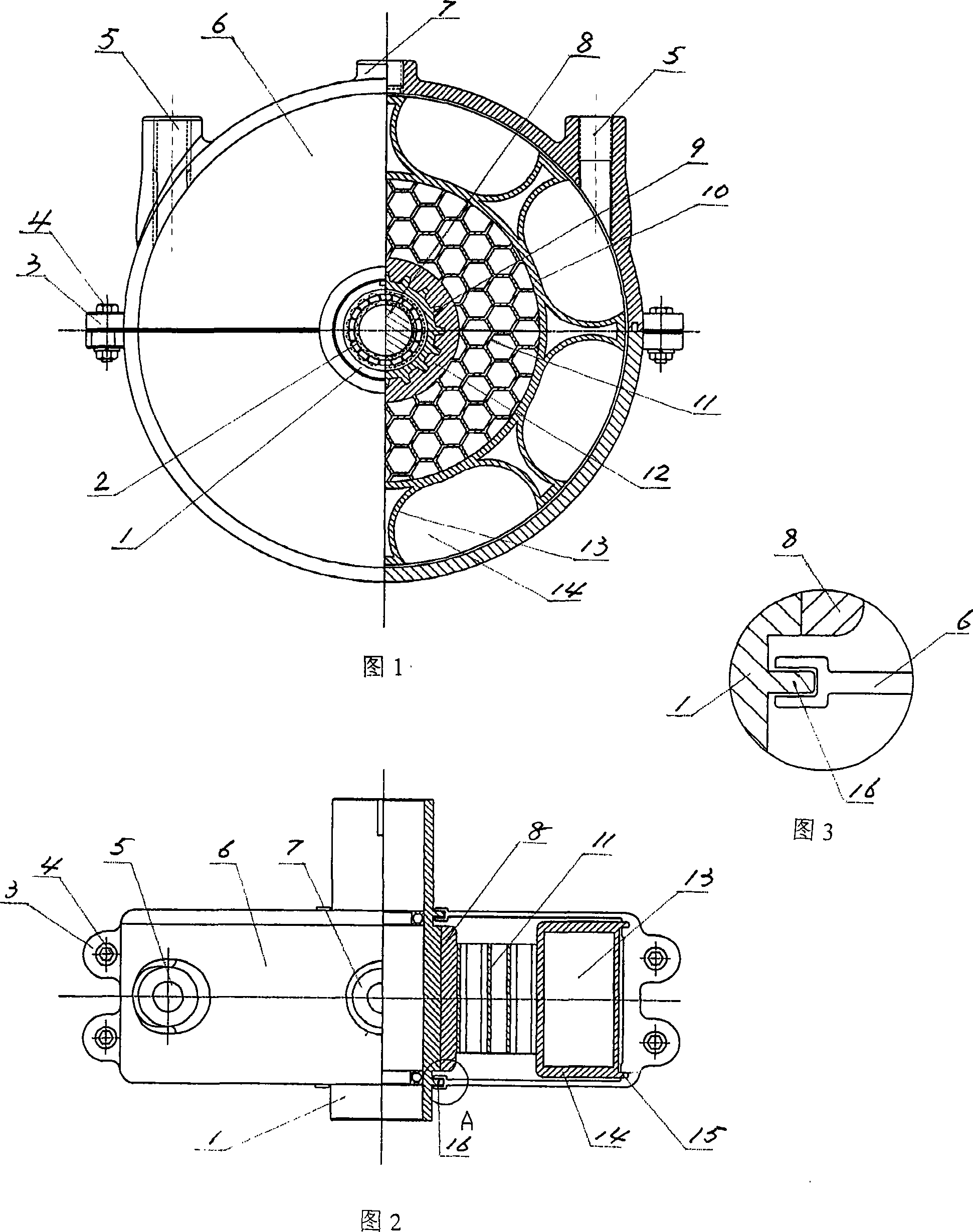
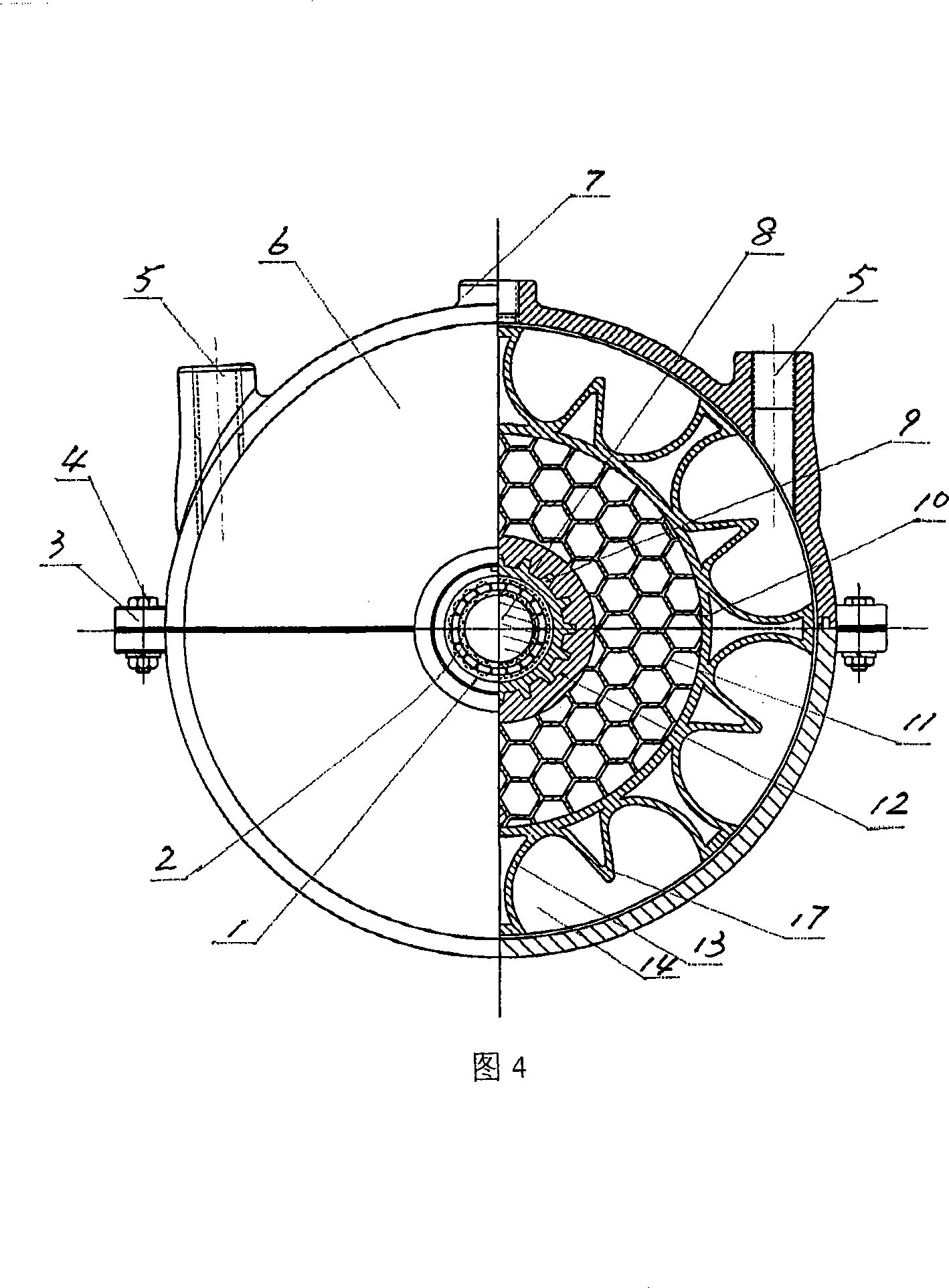
[0013] As shown in FIGS. 1 and 2 , the compressed air motor of the present invention comprises a casing 6 . The shell is cylindrical, and an air inlet 5 and an air outlet 7 are processed on the shell walls around it. The air inlet 5 wherein includes a forward air inlet and a reverse air inlet, the longitudinal centerlines of the two air inlets are parallel, and they are all on the same semicircular shell wall of the shell 6 . And the air outlet 7 is between the two air inlets 5 . Both ends of the shell 6 are provided with a center hole, and a shaft sleeve 1 is installed in the center hole. As shown in Fig. 3, a circumferential groove is processed on the inner circle of the center hole on both ends of the shell 6, and a circumferential boss 16 is processed on the outer circle of the shaft sleeve 1 corresponding to the circumferential groove. The circumferential boss 16 is sealed and movable into the circumferential groove on the inner circle of the center hole of the two end ...


PUM


Abstract

The invention discloses a compressed air engine, comprising a casing. The casing is cylindrical. An air inlet and an air outlet are arranged on casing wall of the casing periphery. Center holes with a shaft sleeve inside are arranged on the casing wall of both casing ends. Both ends of the shaft sleeve protrude outside the casing wall of both casing sides and movably match with the center holes in shape of hermetic closure. A stationary shaft is arranged inside the shaft sleeve. A bearing is arranged between the stationary shaft and the shaft sleeve. An impeller is also arranged inside the casing. The impeller comprises a wheel shaft. An axial hole is arranged on the wheel shaft. The impeller is fixedly sleeved on the shaft sleeve through the axial hole. A supporting ring is arranged outside the impeller. Space is reserved between the supporting ring and the wheel shaft. The supporting ring is connected with the wheel shaft through a supporting rib. An air cavity is distributed evenly on the external circumference. The air cavity port movably matches with the inner wall of the casing periphery in shape of hermetic closure. The compressed air engine has the advantages of simple structure, low production cost, small energy consumption, and good energy-saving, being suitable for various mobile vehicles.

Description

technical field [0001] The invention relates to an engine. Specifically, it is an engine using compressed air as a power source, and is especially suitable for various motor vehicles. Background technique [0002] As is well known in the engine manufacturing industry, conventional compressed air engines contain casings. The shell is cylindrical, with an air inlet and an air outlet on the shell walls around it, and a central hole is arranged on the shell walls at both ends, and a shaft sleeve is arranged in the central hole. The two ends of the shaft sleeve protrude from the shell walls at both ends of the shell, and are movably matched with the central hole in a sealed shape, and are equipped with bearings inside. Inside the housing is an impeller consisting of a shaft and blades evenly distributed around the shaft and directly connected to the shaft. There are two types of blades, flat and spiral. When working, the impact force of the compressed air entering the shell f...

Claims


Application Information

Patent Timeline
IPC IPC(8): F01D1/06F01D5/02F01D9/00F01D25/24
Inventor 李勇强姜春来
Owner WUXI C SOLAR NEW ENERGY TECH
Learn More