
Floating rubber damping vibration attenuation device

A vibration reduction device and damping technology, which is applied in non-rotational vibration suppression, solid separation, chemical instruments and methods, etc., can solve the problems of non-adjustable displacement of rubber pads, limited load weight, low efficiency, etc., and achieve vibration reduction in a wide frequency range Adaptability, simple structure and easy maintenance

Inactive Publication Date: 2008-07-23
NANJING UNIV OF SCI & TECH +1
View PDF0 Cites 10 Cited by
  • Summary
  • Abstract
  • Description
  • Claims
  • Application Information

AI Technical Summary

Problems solved by technology

In the prior art, the devices used for energy absorption and attenuation of vibrating screens and vibrating hopper vibration sources mainly use vibration damping springs, vibration damping pads, composite vibration damping devices, etc., such as: Xinxiang City, Henan Province Hongda Vibration Equipment Co., Ltd. The vibration damping device of the vibrating screen equipment produced by the company only uses a single damping spring to attenuate the energy of the vibration source
Although the structure of the device is simple, there are many problems: (1) it can only bear the load in one direction; (2) the load weight it can bear is limited; (3) the vibration damping of the spring is limited by the frequency of the vibration source; (4) the spring Low energy consumption and low efficiency for vibration reduction
This device is equally simple, but also has the following problems: (1) the load bearing direction is single; (2) the displacement produced by the rubber pad in the vertical direction is not adjustable
However, it also has the disadvantages of single load bearing direction, inability to bear torsion, and unadjustable displacement in the load bearing direction.

Method used


Image

  • Floating rubber damping vibration attenuation device
  • Floating rubber damping vibration attenuation device
  • Floating rubber damping vibration attenuation device

Examples


Embodiment Construction

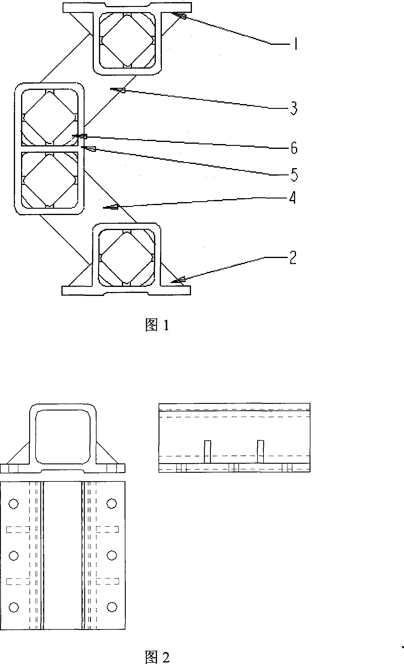
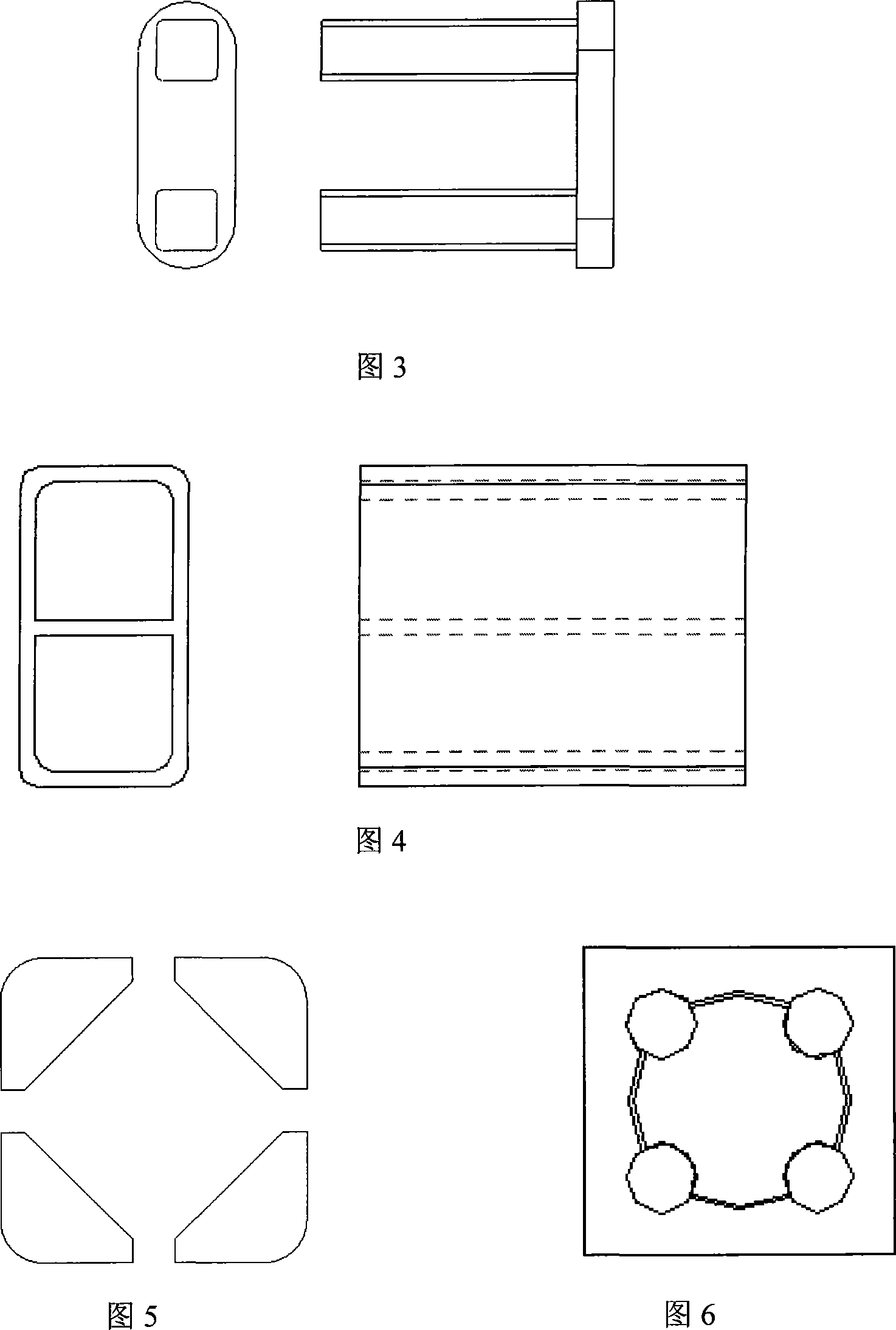
[0014] In conjunction with Fig. 1, the floating rubber damping and vibration reduction device of the present invention, four sets of damping rubber shock absorbing block units 6 are respectively installed in the upper movable support 1, the lower fixed support 2 and the floating box 5, wherein two groups are respectively installed in the floating box 5 in the two holes. The upper swing power arm 3 is hinged with the upper movable support 1 and the floating box 5 respectively, and the lower swing power arm 4 is hinged with the lower fixed support 2 and the floating box 5 respectively.

[0015] Among them, the buffer of the vibration damping device unit 6 adopts the composite vibration damping structure of the upper and lower swing arms 3, 4 and damping rubber, so that the vibration damping device can not only achieve high energy consumption, but also meet the large displacement vibration excited by the main vibration. . The upper and lower swing arms 3, 4 are used to rotate an...


PUM


Abstract

The invention discloses a vibration damping apparatus of floating rubber. The four groups of the rubber vibration damping units of the apparatus are respectively arranged on the upper moving support, the lower fixed support and in the floating box. The upper swinging power arms are respectively hinged with the upper moving support and the floating box, and the lower swinging power arms are hinged with the lower fixed support and the floating box. The vibration damping apparatus adopts high-damping and high energy-dissipation rubber vibration damping units to make sure a big decrease of the peak value when the vibration power caused by the source of vibration is passed to the lower fixed support, and the decrease reaches 50% of the original together with a decrease of more than 40% of the energy, and so the vibration isolation is evident; the upper and lower force arms swing around the floating box in small angles, increasing the displacement of the rubber deformation in a vertical direction; the characteristics of the cross section of the rubber vibration damping units and the special arrangement of the damping vibration and the swinging arms make the apparatus withstand torsions; the special characteristics of the rubber, the structural shape together with the arrangement lead to an adaptability of vibration damping within a wide frequency range.

Description

a technical field [0001] The invention belongs to floating rubber damping and vibration reduction technology, in particular to a rubber damping and vibration reduction device for asphalt mixing and screening equipment and crusher vibration feeding equipment. Two background technology [0002] In the asphalt mixing and screening equipment and the vibrating feeding equipment of the crusher, the vibrating screen and the vibrating hopper box are excited by the vibrating motor to obtain a large vibration energy for the screening and material feeding of incoming materials. In order to prevent the inertial impact force caused by vibration from being transmitted to the frame structure, resulting in the strength damage of the frame and the damage to other devices of the equipment caused by severe vibration, especially when the excitation frequency caused is the same as the natural frequency of the equipment, it will cause The whole equipment produces synchronous vibration, causing re...

Claims


Application Information

Patent Timeline
Patent Type & Authority Applications(China)
IPC IPC(8): F16F15/08B07B1/00B02C23/02
Inventor 钱林方石秀东江剑赖长缨王显会徐亚栋陈龙淼邓昕陆元明陆晏陆国彦任建军孟振军
Owner NANJING UNIV OF SCI & TECH
Learn More