
Optical fiber

A technology of optical fiber and glass optical fiber, which is applied in the direction of light guides, optics, optical components, etc., can solve the problems of easy microbending and achieve the effect of less constraints

Inactive Publication Date: 2008-07-23
FURUKAWA ELECTRIC CO LTD
View PDF1 Cites 8 Cited by
  • Summary
  • Abstract
  • Description
  • Claims
  • Application Information

AI Technical Summary

Problems solved by technology

[0016] In particular, microbending is very likely to occur when water bubbles occur at the interface between the glass optical fiber and the main layer 13 or near the glass optical fiber.

Method used


Image

  • Optical fiber
  • Optical fiber
  • Optical fiber

Examples


Embodiment Construction

[0038] Next, the optical fiber of the present invention will be described in detail using the drawings.

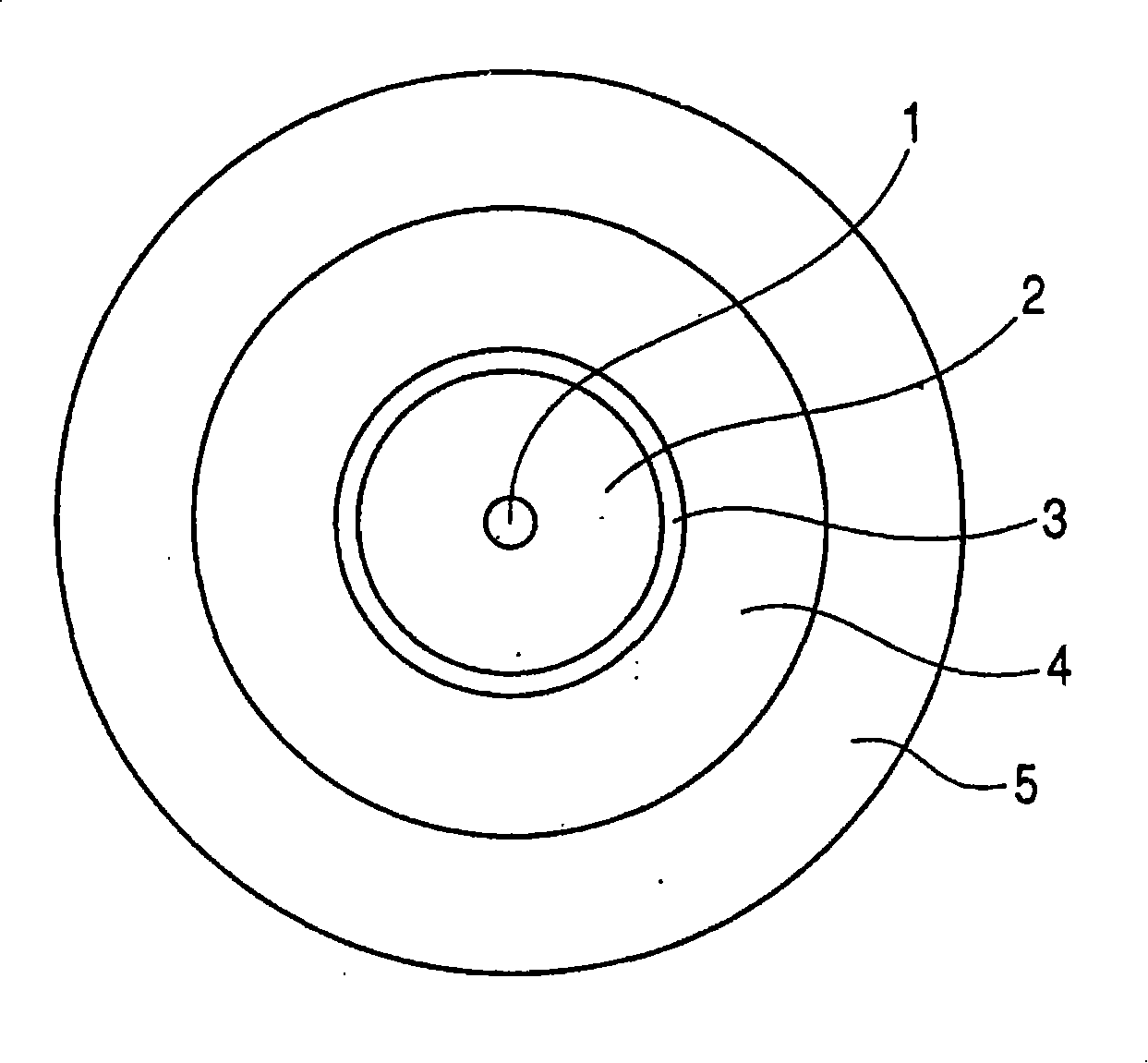
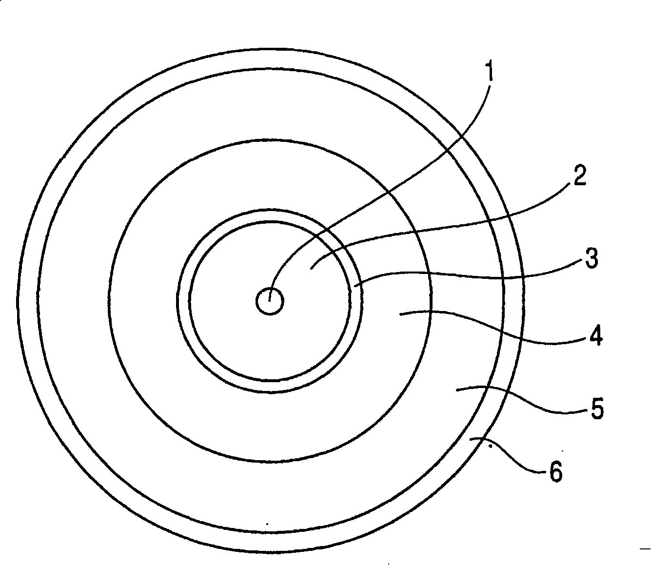
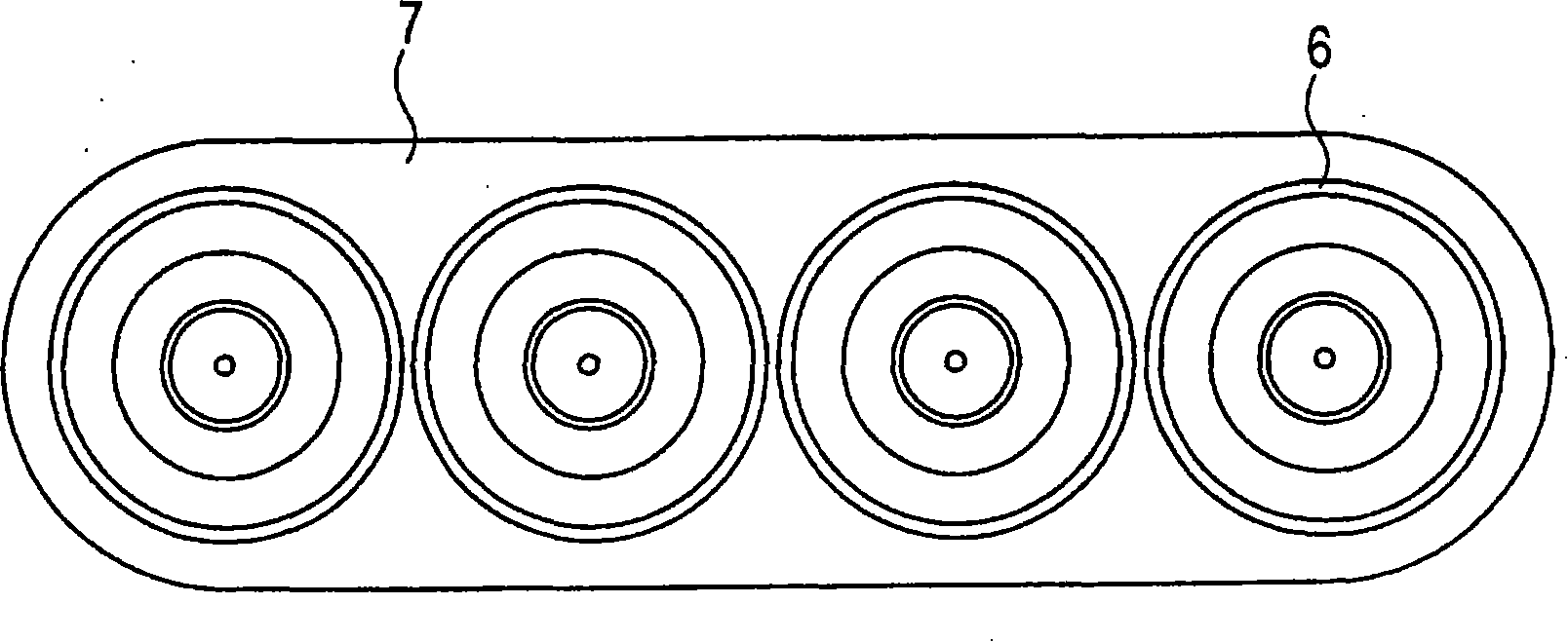
[0039] figure 1 is a schematic cross-sectional view showing an embodiment of the optical fiber of the present invention. figure 1 The shown optical fiber of the present invention includes: a glass fiber with a core 1 through which optical signals can pass through at the center and a cladding 2 at its periphery; a primary protection layer 3 coated on the glass fiber; formed on the primary protection A secondary protective layer 4 on the layer 3; and a tertiary protective layer 5 further formed on the periphery of the secondary protective layer 4, characterized in that the glass transition temperature Tg of the primary protective layer 3 is greater than -20°C, and at 10°C Hereinafter, the glass transition temperature Tg of the secondary protective layer 4 is 10° C. or lower, and the Tg of the primary protective layer 3 is higher than the Tg of the secondary protective lay...


PUM

PropertyMeasurementUnit
glass transition temperatureaaaaaaaaaa
melting pointaaaaaaaaaa

Abstract

The present invention provides an optical fiber in which composites constructing its coating are not complicated, so, there is also little constraint in view of production, and, moreover, delamination between a glass optical fiber and a primary layer, and a bubble in the primary layer hardly arise. The optical fiber of the present invention is an optical fiber which has a glass optical fiber which has a core 1, which passes an optical signal, in a center portion, and a cladding 2 surrounding this, a primary protective layer 3 made to coat the glass optical fiber, a secondary protective layer 4 applied on this primary protective layer 3, and a third protective layer 5 applied to an outer periphery of this secondary protective layer 4, wherein glass transition temperature of the primary protective layer 3 is made to be higher than -20°C and 10°C or lower, glass transition temperature of the secondary protective layer 4 is made to be -10°C or less, and the glass transition temperature of the primary protective layer 3 is set higher than that of the secondary protective layer 4.

Description

technical field [0001] The present invention relates to an optical fiber having a highly reliable cladding layer in the aspect of an optical fiber for transmitting optical signals. Background technique [0002] Conventional optical fibers, generally speaking, have such Figure 4 In the structure shown, a glass optical fiber made of silica glass having a core 1 through which an optical signal can pass at the center and a cladding 2 disposed on the outside thereof is covered with a soft main layer 13, and the main layer 13 It is also coated with a hard secondary layer 14. [0003] In general, the main layer 13 uses a UV-curable resin with a Young's modulus of 3 MPa or less, and the sub-layer 14 uses a UV-curable resin with a Young's modulus of 500 MPa or higher. [0004] However, the material properties of a polymer material vary greatly with a glass transition temperature (hereinafter simply referred to as Tg) as a boundary. In particular, efforts have been made for optical...

Claims


Application Information

Patent Timeline
Patent Type & Authority Applications(China)
IPC IPC(8): G02B6/44
CPCG02B6/4402C03C25/1065G02B6/4404
Inventor 中岛康雄田中广树新子谷悦宏望月浩二冈田光范
Owner FURUKAWA ELECTRIC CO LTD
Learn More