Glass hot-bending die as well as manufacturing method and application thereof

A glass and mold technology, applied in glass hot bending molds and its manufacturing method and application field, can solve the problems of concentrated energy loss, high mold production cost, low production efficiency, etc., to reduce heat absorption, reduce production costs, The effect of improving productivity

Active Publication Date: 2013-10-23
CHINA BUILDING MATERIALS ACAD +1
View PDF3 Cites 2 Cited by
  • Summary
  • Abstract
  • Description
  • Claims
  • Application Information

AI Technical Summary

Problems solved by technology

[0005] Existing glass hot-bending molds are large in size and weight, and the production cost of the mold is high; the glass hot-bending process needs to be carried out at high temperature, and the mold absorbs a large amount of heat at high temperature, and is prone to deformation. It cannot be used repeatedly and the glass backplane cannot be guaranteed. The molding accuracy cannot meet the requirements of the focal length and spot size of the mirror design, resulting in the loss of concentrating energy; the mold temperature rises and cools slowly, and the molding process of the glass backplane takes a long time and the production efficiency is low.

Method used


Image

  • Glass hot-bending die as well as manufacturing method and application thereof
  • Glass hot-bending die as well as manufacturing method and application thereof

Examples


Embodiment 1

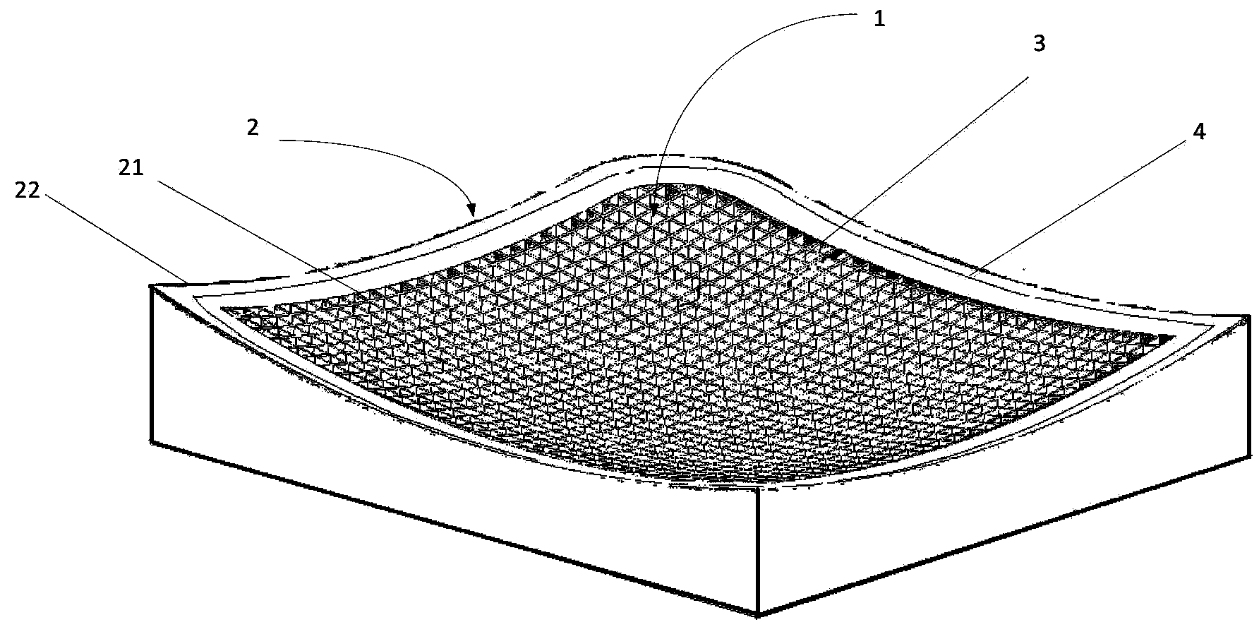
[0026] The embodiment of the present invention provides a glass hot bending mold, see figure 1 , the glass hot bending mold includes a main body 1 and a glass edge hot bending part 2 . The main body 1 is provided with a plurality of through holes 3 , and the through holes 3 pass through the upper surface and the lower surface of the main body 1 . The glass edge hot bending part 2 is a frame-type structure with uniform material, which can be covered on the periphery of the main body 1 by welding or integral molding, etc., and is used for hot bending the edge part of the glass. The size of the glass edge hot bending part 2 is determined by the The size of the hot-bent glass determines that when the glass is placed on the mould, the outer frame of the hot-bending portion 2 of the glass edge coincides with the edge of the glass or is located at the periphery of the glass, preferably at the edge of the glass. Periphery, its inner frame edge is located inside the edge of the glass,...

Embodiment 2

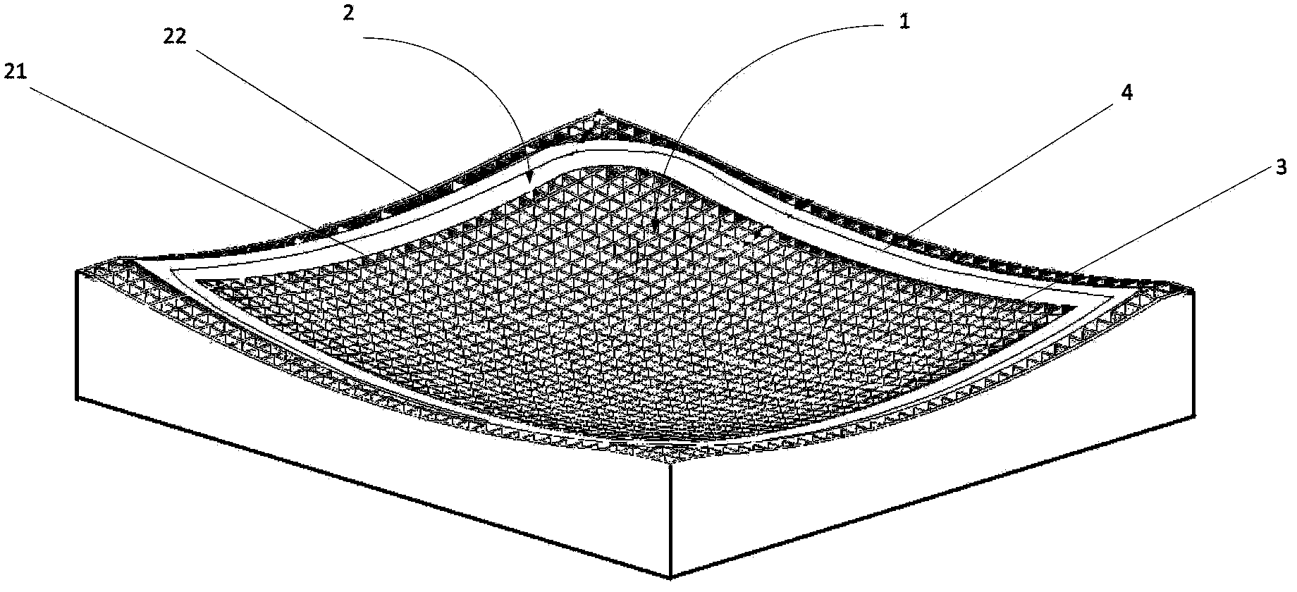
[0032] The embodiment of the present invention provides a glass hot bending mold, see figure 2 , the glass hot bending mold includes a main body 1 and a glass edge hot bending part 2 . The main body 1 is a hollow structure uniformly provided with a plurality of through holes 3, the through holes 3 run through the upper surface and the lower surface of the main body 1, and a groove (not shown in the figure) is also provided on the main body 1, and the opening of the groove Upward, the size of the groove matches the size of the glass edge hot bending part 2 for accommodating the glass edge hot bending part 2 , preferably, the groove of the main body 1 is also provided with a through hole 3 . The glass edge hot bending part 2 is a frame structure with uniform material, which is used to support and heat bend the edge part of the glass. Its size is determined by the size of the glass to be bent. When the glass is placed on the mold, the glass edge is bent The outer frame edge of ...

Embodiment 3

[0042] The embodiment of the present invention provides the manufacturing method of embodiment 2, the method comprising:

[0043] Step 1: respectively casting hot bending mold main body 1 and glass edge hot bending part 2;

[0044] see figure 2 , according to the surface design size of the molding surface, the casting mold of the mold main body 1 and the glass edge hot bending part 2 is processed, wherein the main body 1 is a hollow structure with a plurality of through holes 3 evenly provided, and the glass edge hot bending part 2 is made of uniform material The frame structure, the upper surface of the main body 1 and the upper surface of the glass edge hot bending part 2 are all processed according to the design size of the molding surface.

[0045] Step 2: Open a groove on the upper surface of the main body 1;

[0046] According to the size of the glass, determine the position where the glass to be bent is placed on the main body 1, and open a groove on the main body 1 ...


PUM

PropertyMeasurementUnit
thicknessaaaaaaaaaa
lengthaaaaaaaaaa
depthaaaaaaaaaa

Abstract

The invention discloses a glass hot-bending die as well as a manufacturing method and application of the glass hot-bending die, belonging to the technical field of solar energy utilization. The glass hot-bending die comprises a main body and a frame-shaped glass edge hot-bending part, wherein the main body has a plurality of through holes which pass through the upper and lower surfaces of the main body; the frame-shaped glass edge hot-bending part is connected with the main body; a glass forming surface is formed by the upper surface of the frame-shaped glass edge hot-bending part together with the upper surface of the main body. According to the glass hot-bending die, by forming the through holes in the main body part of the glass hot-bending die, materials used by the glass hot-bending die are reduced, the die production cost is lowered, the heat that the die absorbs is reduced, the uniform glass heating and forming in the hot-bending process are facilitated, the radiation of the heat of the die is facilitated, and both the service life of the die is prolonged and the forming precision of glass is ensured; due to the existence of the through holes, the hot-bending die is good in heat circulation in the hot-bending process, a plurality pieces of glass can be hot-bent simultaneously, the production efficiency is greatly improved, and due to the arrangement of the through holes, the weight of the die is reduced, and the die can be conveniently hoisted and transported.

Description

technical field [0001] The invention relates to a glass hot-bending mold and its manufacturing method and application, belonging to the technical field of solar energy utilization, in particular to a glass hot-bending mold used for a reflective part of a solar heat utilization system. Background technique [0002] Solar collectors are the key components of various solar heat utilization systems. Whether it is solar water heaters, solar cookers, active solar houses, solar greenhouses or solar drying, solar industrial heating, solar thermal power generation, etc., solar collectors are inseparable, and solar collectors are used as the power or core components of the system. . [0003] Solar collectors use reflectors to gather sunlight. At present, according to the different types of reflectors, solar collectors are divided into trough collectors, tower collectors, dish collectors, and Fresnel collectors. device etc. The reflector of a solar collector is generally composed of...

Claims


Application Information

Patent Timeline
Patent Type & Authority Applications(China)
IPC IPC(8): C03B23/025
CPCY02P40/57
Inventor 穆元春徐志伟付静肖昊江陈玮左岩张凡刘超英张洋
Owner CHINA BUILDING MATERIALS ACAD
Why Eureka
Try Eureka