Head stereotaxic apparatus

A locator and head technology, which is applied in the field of head stereotaxic instruments, can solve the problems of complex and bulky position adjustment structure of the headrest mechanism of the locating device

Inactive Publication Date: 2008-07-30
徐屹
View PDF2 Cites 16 Cited by
  • Summary
  • Abstract
  • Description
  • Claims
  • Application Information

AI Technical Summary

Problems solved by technology

The defect of this therapeutic instrument is that the position adjustment of its positioning device and the adjustment structure of the headrest mechanism position are complicated a

Method used


Image

  • Head stereotaxic apparatus
  • Head stereotaxic apparatus
  • Head stereotaxic apparatus

Examples


Embodiment Construction

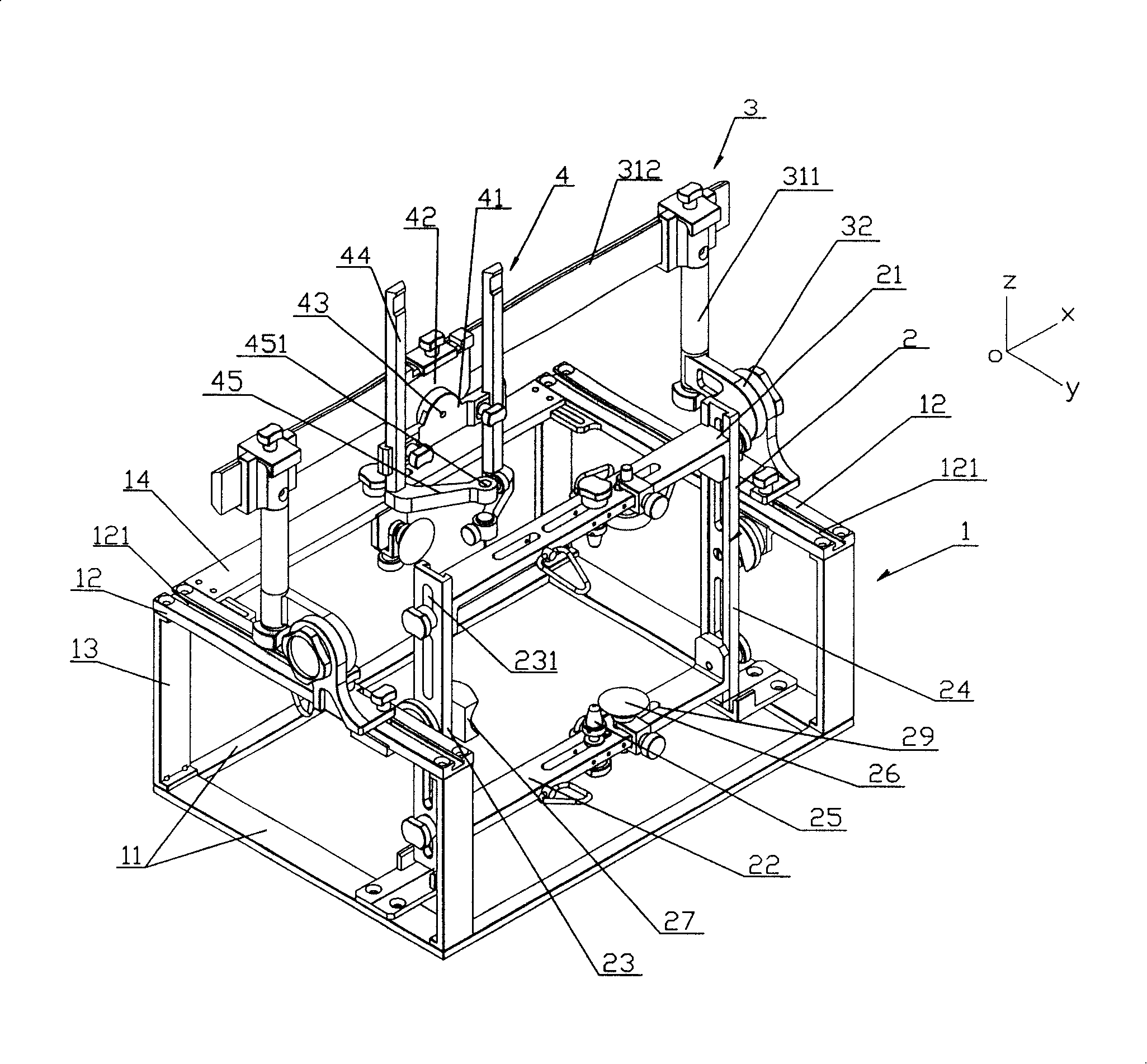
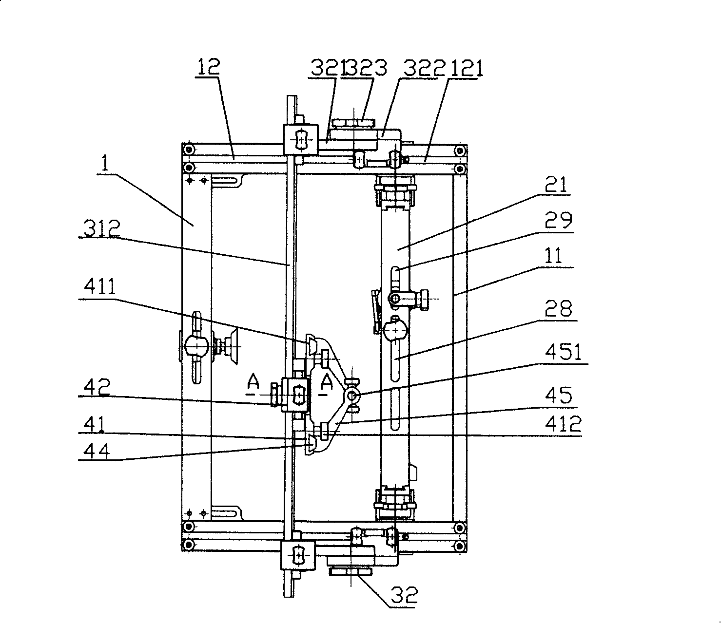
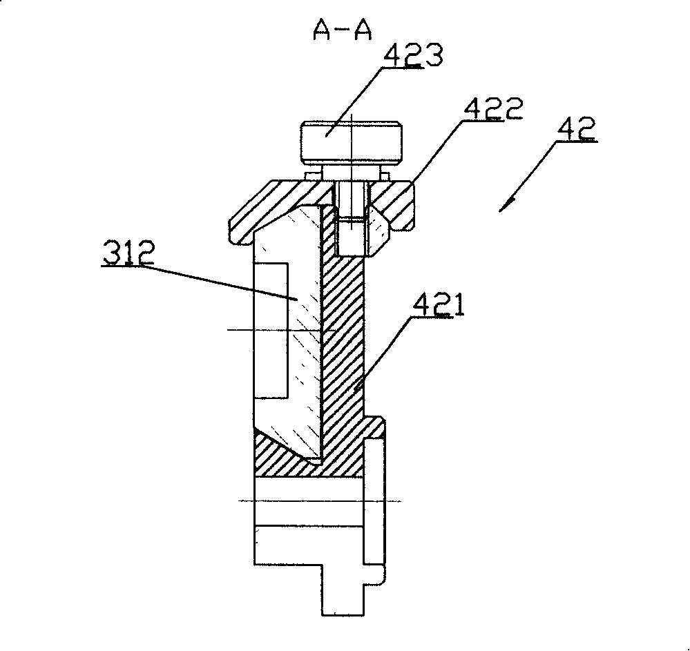
[0029] see figure 1 , figure 2 , image 3 , the figure shows the structure of a specific embodiment of the stereotaxic instrument of the present invention, the stereotaxic instrument includes a bracket 1, a head fixation device 2, a positioning device 3 and a puncture device 4 four parts, wherein: the bracket 1 includes a base plate 11. The two horizontal upper guide rails 12 are supported by four pillars 13 and arranged parallel to the Y-axis direction. In order to improve the rigidity of the bracket, the rear ends of the two upper guide rails 12 are connected to a rod 14. The upper guide rails 12 are provided with a Inverted T-shaped track 121;

[0030] The head fixing device 2 is located between the two upper guide rails 12 of the support 1, and is located near the front of the upper guide rail 12. The head fixing device 2 consists of an upper plate 21, a lower plate 22, a left side plate 23 and a right side The square or rectangular frame structure that plate 24 forms,...


PUM


Abstract

The invention discloses a head solid locator, belonging to a technical field of medical machinery which includes a bracket, the upper surface of which is provided with a pair of lead rails arranged in parallel along the horizontal direction, a head fixing device which is used for confirming a head scanning datum layer surface and leading the scanning datum layer surface to be vertical to the horizontal upper lead rails, and is arranged on the front side between the two horizontal upper lead rails, one locating device which includes a door-shaped bracket and two lower ends of two upright posts of the door-shaped bracket are provided with an articulating device which can lead the door-shaped bracket to rotate along an X-shaft direction. The lower end of the articulating device is connected with a slide block arranged on the upper lead rails. A cross beam at the upper end of the door-shaped bracket is provided with a puncturing device which can slide along the cross beam. The invention solves the defect that the head locating device in the prior art can not realize 3D rotation and moving and has the advantages of simple structure and accurate location.

Description

technical field [0001] The invention relates to the technical field of medical devices, in particular to a head stereotaxic instrument used for puncturing and treating head lesion parts. Background technique [0002] Internal diseases of the brain, such as hematoma, abscess and cyst, usually require surgery to remove or cure these lesions. At present, ultrasound is used to treat thrombosis of cerebral thrombus. Whether it is puncture drainage or ultrasonic thrombolysis, the most important The problem is to determine the exact location of the lesion. The more advanced equipment used to determine the location of craniocerebral lesions is to use CT / MR machines to take pictures of the head, and determine the location of the lesions according to the patterns on the photos. However, since the photos are two-dimensional figures, it is still difficult to accurately reproduce the location of the lesion on the head during the operation, so experienced operators are required to perfor...

Claims


Application Information

Patent Timeline
IPC IPC(8): A61B6/04A61B19/00A61B17/00A61B90/14
Inventor 徐屹
Owner 徐屹
Why Eureka
Try Eureka