
Solution-processable phosphorescent materials

An optical device, organometallic technology, applied in the field of new materials

Inactive Publication Date: 2008-07-30
CAMBRIDGE ENTERPRISE LTD
View PDF4 Cites 0 Cited by
  • Summary
  • Abstract
  • Description
  • Claims
  • Application Information

AI Technical Summary

Problems solved by technology

These materials are not capable of luminescence which is mainly phosphorescence

Method used


Image

  • Solution-processable phosphorescent materials
  • Solution-processable phosphorescent materials
  • Solution-processable phosphorescent materials

Examples


Embodiment Construction

[0170] test part

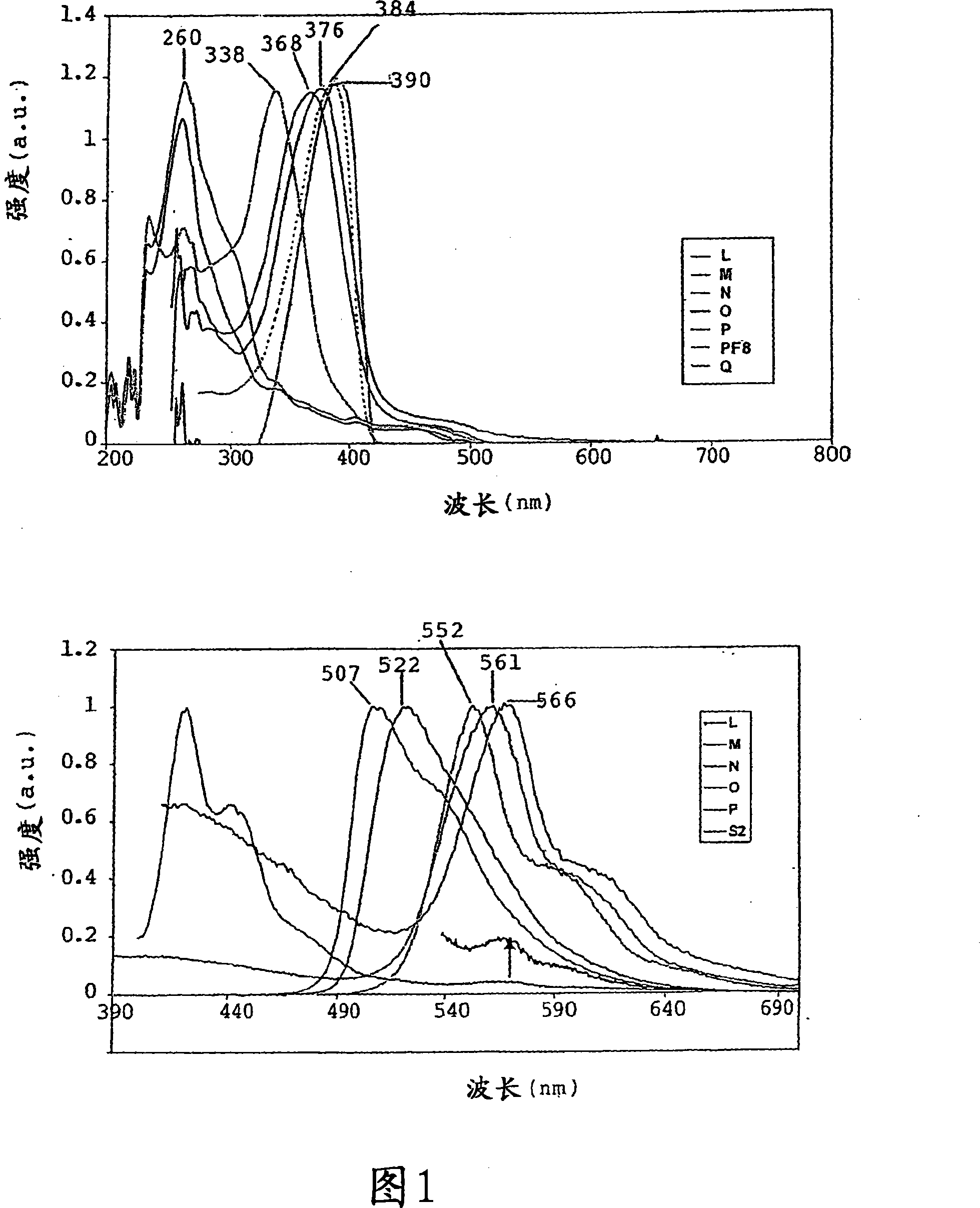
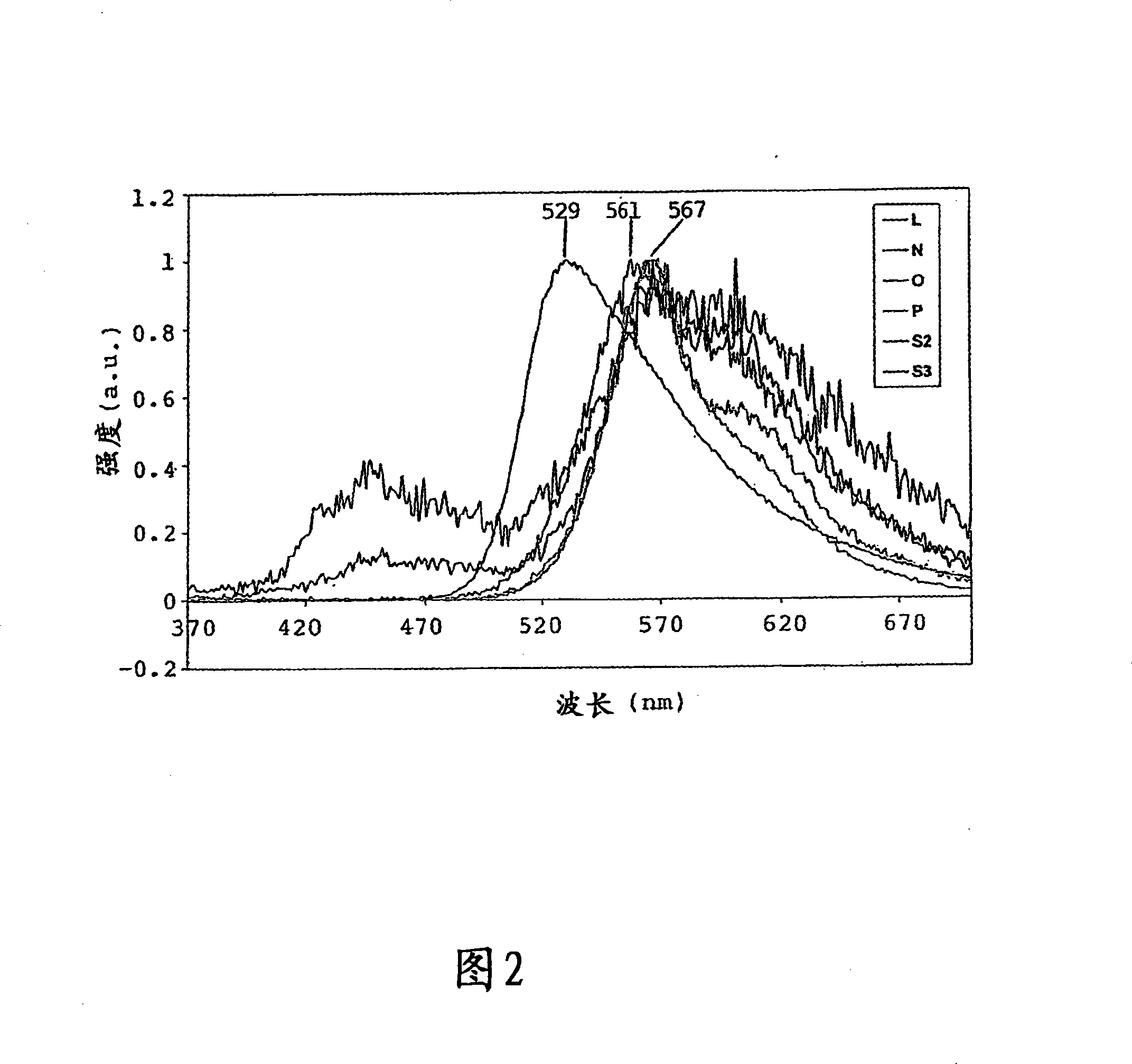
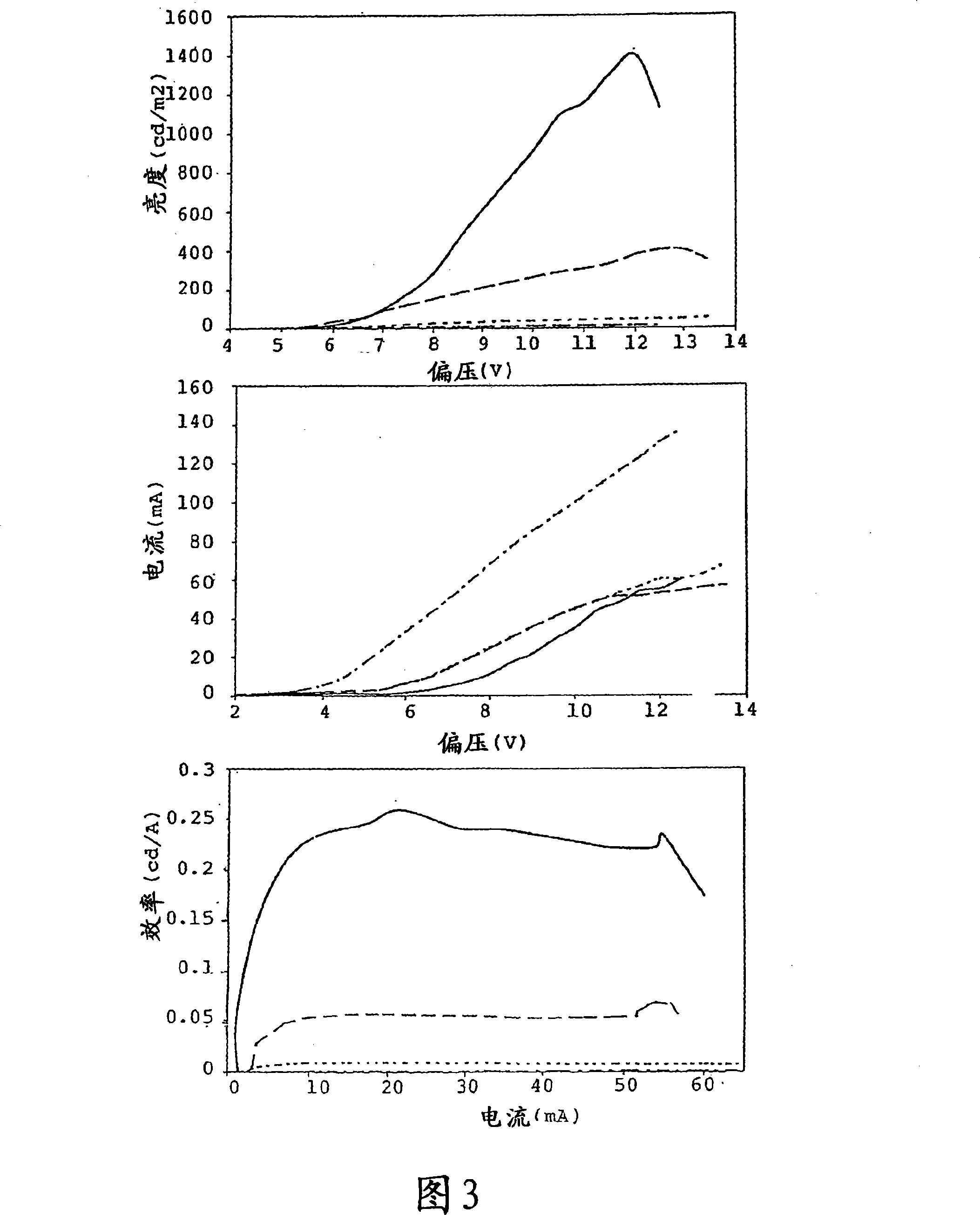
[0171] To demonstrate the invention, the attachment of the subsequent fluorenyl segment to the 4-position of the ligand of the bicyclometalated iridium phosphor was investigated. After attachment of monofluorenyl substituents, the energy levels of the novel phosphors were shown to be complementary to polyfluorene. It was also shown that the gradual incorporation of more fluorenyl segments into the phosphor results in a gradual improvement in its performance as an emissive layer in OLED device structures. The polyaddition of phosphors has been further extended to the development of polyfluorenyl-phosphor hybrid systems.

[0172] test

[0173] General information

[0174] All reactions and manipulations were routinely performed under argon or nitrogen atmosphere using standard Schlenk techniques or a glove box. Before use, from CaH 2 Acetonitrile and dichloromethane were distilled over, and toluene and THF were distilled over Na. Before use, mix water, g...


PUM


Abstract

The present invention relates to a solution-processable phosphorescent material, in particular to a material capable of emitting light, comprising: a polymer or oligomer; and an organometallic group, characterized in that the polymer or oligomer is at least partly The conjugated and organometallic groups are covalently bonded to the polymer or oligomer and the nature, position and / or ratio of the polymer or oligomer and organometallic groups in the material are chosen such that the emission is predominantly phosphorescent.

Description

[0001] This divisional application is a divisional application based on the Chinese patent application with application number 03814689.4, application date of April 24, 2003, and invention title "solution processable phosphorescent material". technical field [0002] The present invention relates to a novel material capable of emitting light; to a method for preparing the novel material and to an application of the novel material. Background technique [0003] Light-emitting conjugated polymers are a new class of technologically important materials that will be used in light-emitting display devices for next-generation information technology-based consumer products. The primary interest in the use of polymers, as opposed to inorganic semiconducting materials and organic dye materials, lies in the scope of low-cost fabrication using solution processing of film-forming materials. Since the last decade, much effort has been devoted to improving the emission efficiency of organi...

Claims


Application Information

Patent Timeline
IPC IPC(8): C09K11/06H05B33/14H01L51/50C07D409/04C07F15/00C08G61/02C08G73/06C08G85/00H01L51/30
CPCC08G61/02C09K11/06C09K2211/1416C09K2211/1425C09K2211/1433C09K2211/145C09K2211/1458C09K2211/1466C09K2211/1483C09K2211/185H05B33/14H10K85/115H10K85/151H10K85/342H10K50/11H10K2101/10
Inventor A·赫尔梅斯A·萨恩迪C·威廉姆斯A·克赫勒N·埃文斯
Owner CAMBRIDGE ENTERPRISE LTD
Learn More