Variable coupling of high pressure rotor and low pressure rotor of turbofan engine

一种涡扇发动机、高压转子的技术,应用在发动机元件、发动机功能、机器/发动机等方向,能够解决大发电机、不实际等问题,达到电力工作频率合适、尺寸合适、大容量的效果

Inactive Publication Date: 2008-07-30
GENERAL ELECTRIC CO
View PDF1 Cites 18 Cited by
  • Summary
  • Abstract
  • Description
  • Claims
  • Application Information

AI Technical Summary

Problems solved by technology

Advocating such a low-speed mechanical power source without transformation results in impractically large generators

Method used


Image

  • Variable coupling of high pressure rotor and low pressure rotor of turbofan engine
  • Variable coupling of high pressure rotor and low pressure rotor of turbofan engine
  • Variable coupling of high pressure rotor and low pressure rotor of turbofan engine

Examples


Embodiment Construction

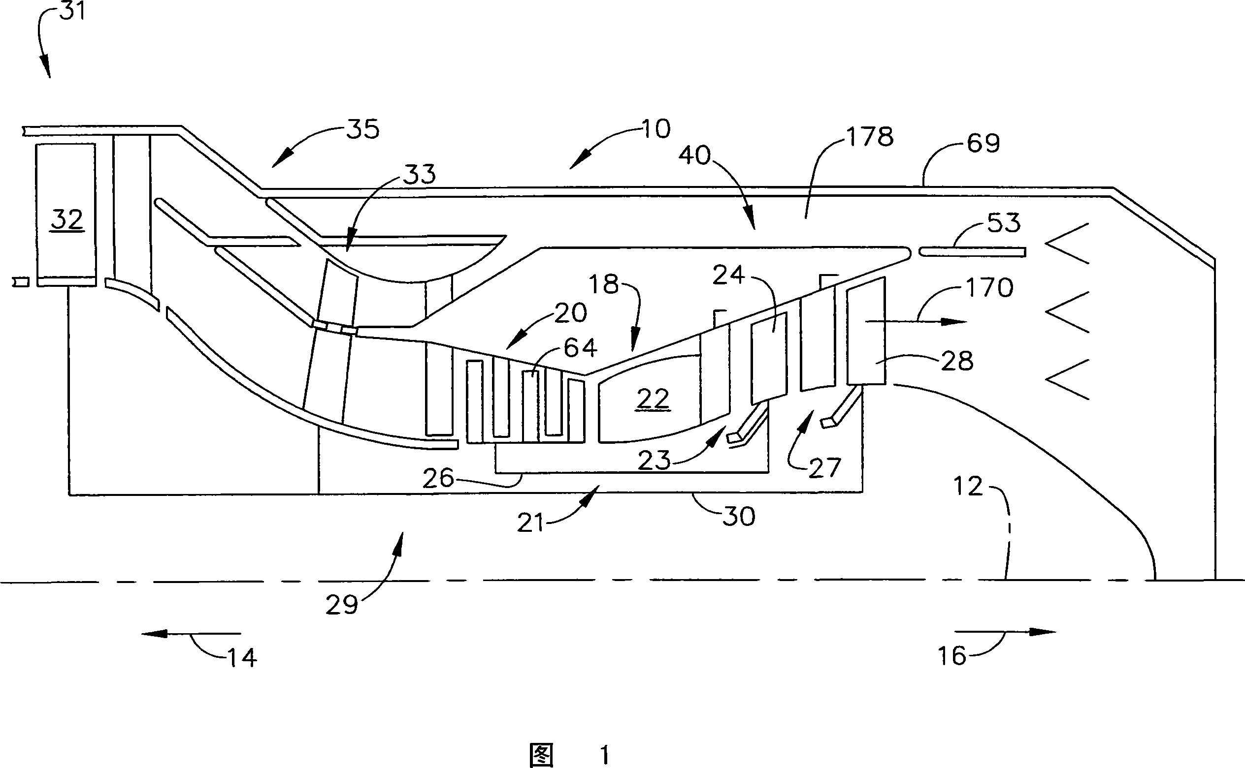
[0025] Shown in FIG. 1 is an exemplary turbofan engine 10 having a generally axially extending axis or centerline 12 extending generally in a forward direction 14 and an aft direction 16 . The ducted turbofan engine 10 includes a core engine 18 (also referred to as a gas generator) including a high pressure compressor 20, a combustor 22, and a high pressure turbine (HPT) 23 having a row of high pressure turbine blades 24, All arranged in series, axial flow relationship. High pressure compressor blades 64 of high pressure compressor 20 are fixedly connected in driving engagement to high pressure turbine blades 24 by a larger diameter annular core motor shaft 26 coaxially disposed about centerline 12 of engine 10 to create high pressure rotor 21.

[0026] A combustor 22 in the core engine 18 mixes pressurized air from the high pressure compressor 20 with fuel and ignites the resulting fuel and air mixture to produce combustion gases. Some work is extracted from these gases by ...


PUM


Abstract

A system for transferring mechanical torque variably between a plurality of rotating machines in a turbofan engine (10). Two devices are used, where the first device relies upon magnetic properties of a planetary magnetic gearbox (50) to couple the magnetic machines. The second device is used to variably control the torque transfer between the magnetic machines. The system couples rotating shafts(52, 54) rotating at differing speeds within a turbofan engine (10) for controllably transferring power. To transfer power in the system, a fixed gear ratio is obtained by coupling the relatively high- and low-speed engine shafts (52, 54) to an epicyclic magnetic gearbox (50).

Description

technical field [0001] The present invention relates to methods and apparatus for coupling of rotating machines, and more particularly to the coupling of high pressure (HP) and low pressure (LP) turbine shafts of turbofan machines. Background technique [0002] A gas turbine engine usually consists of one or several compressors followed in sequence by a combustor and high and low pressure turbines. The engine components are arranged in series flow communication and disposed about the centerline of the longitudinal axis of the engine within the annular casing. The compressor is driven by each turbine and compressor air during operation. The compressor air is mixed with fuel and ignited in the combustor to produce hot combustion gases. The combustion gases flow through high and low pressure turbines that extract energy generated by the hot combustion gases to drive the compressor and generate auxiliary output power. [0003] This engine power is transmitted as both shaft po...

Claims


Application Information

Patent Timeline
Patent Type & Authority Applications(China)
IPC IPC(8): F02C7/36
CPCF05D2220/50F05D2260/40311F16H37/0826F05B2260/404F05D2260/404F02C3/113Y10S74/04F02C7/36F05B2260/40311
Inventor J·M·凯恩M·V·德雷克塞尔J·D·范丹
Owner GENERAL ELECTRIC CO
Why Eureka
Try Eureka