Method for eliminating color difference of twisting type liquid crystal wave-front corrector

A wavefront corrector and liquid crystal correction technology, applied in the field of adaptive optics, can solve the problems of high cost and complicated production

Inactive Publication Date: 2008-07-30
CHANGCHUN INST OF OPTICS FINE MECHANICS & PHYSICS CHINESE ACAD OF SCI
View PDF0 Cites 2 Cited by
  • Summary
  • Abstract
  • Description
  • Claims
  • Application Information

AI Technical Summary

Problems solved by technology

However, the system is

Method used


Image

  • Method for eliminating color difference of twisting type liquid crystal wave-front corrector
  • Method for eliminating color difference of twisting type liquid crystal wave-front corrector
  • Method for eliminating color difference of twisting type liquid crystal wave-front corrector

Examples


specific Embodiment approach 1

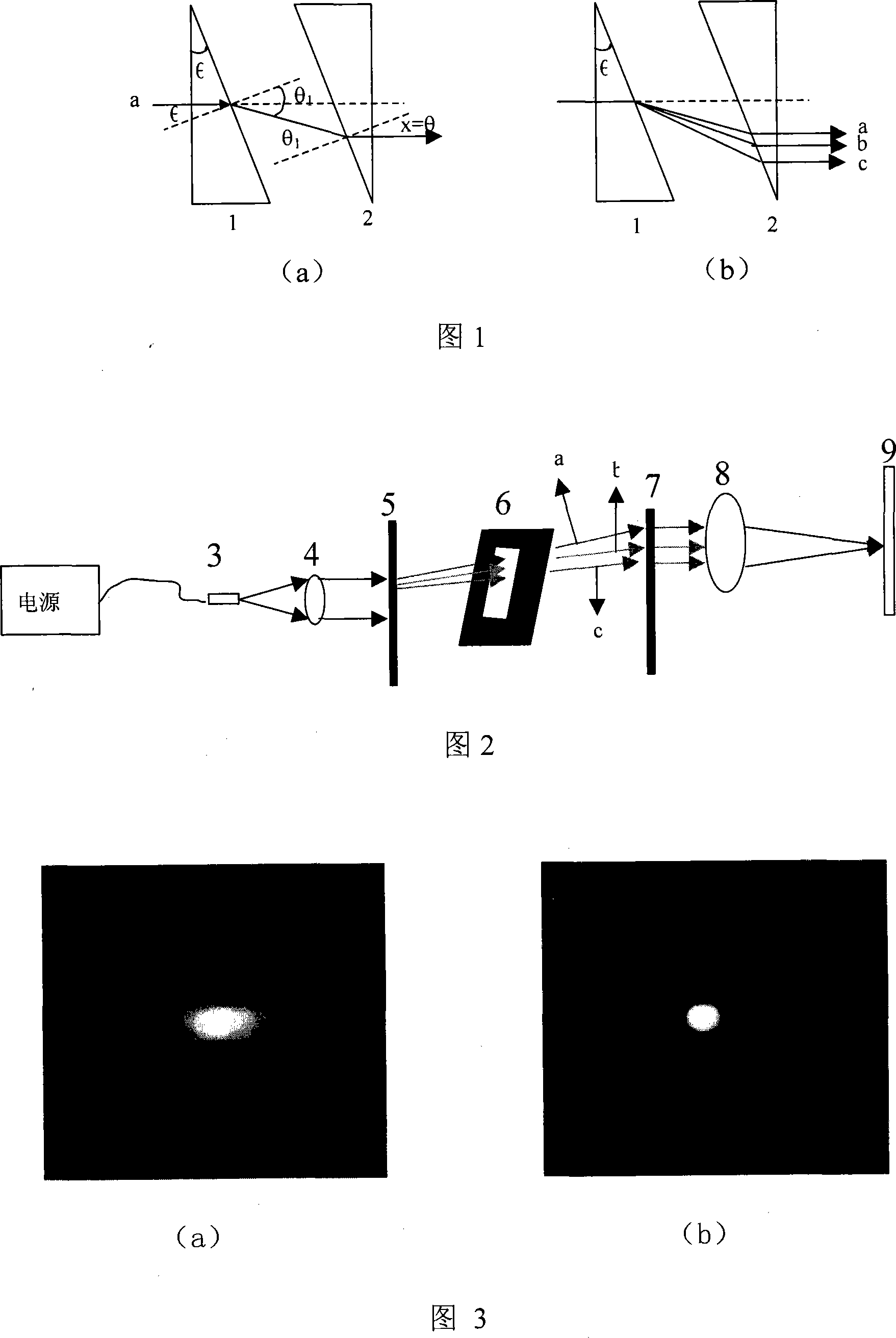
[0024] The optical path structure of Embodiment 1 of the present invention is as shown in Figure 2: by fiber bundle light source 3, first lens 4, first blazed grating 5, pinhole filter 6, second blazed grating 7, second lens 8 and receiving Screen 9 constitutes. The optical fiber bundle light source 3 is placed at the focus position of the first lens 4, so that the light passing through the first lens 4 becomes parallel light; the parallel light beam passes through the first blazed grating 5 to generate dispersion, and the pinhole filter 6 filters out stray light, Then through the second blazed grating 7 opposite to the first blazed grating 5 , the dispersed light is corrected into parallel light; the parallel light is incident on the second lens 8 and is converged and imaged on the receiving screen 9 . The lenses used in the system are all achromatic lenses.

specific Embodiment approach

[0025] In order to further understand the first embodiment of the present invention, the parameters and implementation process of each element in the first embodiment are described in detail below:

[0026] 1) The optical fiber bundle light source 3 is a white light, that is, a visible light source, with a light output diameter of 1 mm and a diameter of each optical fiber of 25 μm.

[0027] 2) The parameters of the first lens 4 and the second lens 8 are the same, both have an aperture of 20mm and a focal length of 300mm.

[0028] 3) The pinhole filter 6 is a square hole filter with tunable light output area, which filters out, that is, only allows the first-order diffracted light of the first blazed grating 5 to pass through.

[0029] 4) The first blazed grating 5 and the second blazed grating 7 have the same parameters, are transmission type, and are blazed gratings composed of isosceles triangles with 100 lines / mm.

[0030] 5) The receiving screen 9 is hard white paper for ...

specific Embodiment approach 2

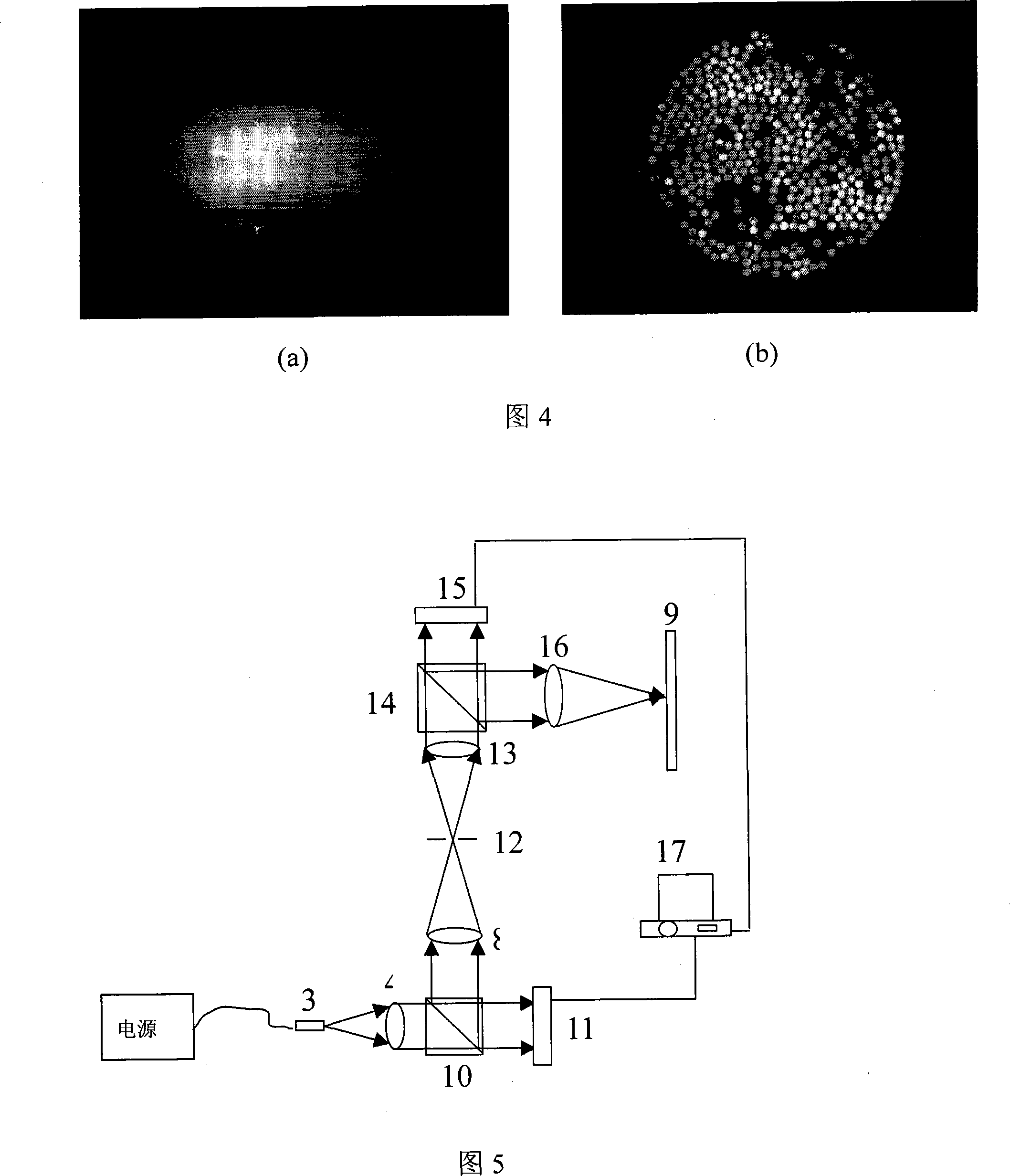
[0036] The optical path structure of the second embodiment of the present invention is as shown in Figure 5: by the fiber bundle light source 3, the first lens 4, the second lens 8, the receiving screen 9, the first beam splitter 10, the first liquid crystal screen 11, the aperture A filter 12, a third lens 13, a second beam splitter 14, a second liquid crystal screen 15, a fourth lens 16 and a computer 17 are composed. The optical fiber bundle light source 3 is placed at the focus position of the first lens 4, so that the light passing through the first lens 4 becomes parallel light; the parallel light beam is incident on the first liquid crystal screen 11 through the beam splitter 10, and the kinoform method is used to generate On the liquid crystal screen 11, a blazed grating is applied by a computer 17 to generate dispersion, and the dispersed reflected light is reflected to the second lens 8 by the beam splitter, and then the first-order diffracted light is filtered out by...


PUM


Abstract

The invention belongs to the field of adaptive optical technique and relates to a method for eliminating the chromatic aberration of a twisted liquid crystal-based wave-front corrector. During the process of wave surface correction with the twisted liquid crystal-based wave-front corrector, the light polarization of the liquid crystal layer may change and a part of the light emerges without correction, and the correction effect is poor. In order to filter the non-corrected stray light, a liquid crystal blazed grating is applied to the twisted liquid crystal-based wave-front corrector based on Kinoform, to allow the polarized light corrected by the liquid crystal layer to diffract in the blazing direction and to filter off the non-corrected stray light. But after applying the blazed grating to the twisted liquid crystal-based wave-front corrector, light beams of different wavelengths may be dispersed in the liquid crystal layer due to the difference in refractive index, producing images with chromatic aberration. The invention also utilizes a liquid crystal blazed grating that has the same parameter and is conjugated in position with the previous blazed grating and arranged behind the twisted liquid crystal-based wave-front corrector, so that the color dispersion of the twisted liquid crystal-based wave-front corrector is eliminated to ensure good quality of images.

Description

technical field [0001] The invention belongs to the technical field of adaptive optics, and relates to a combination technology of optical elements such as a twisted liquid crystal wavefront corrector, a blazed grating and an achromatic lens, and specifically a method for eliminating chromatic aberration of the twisted liquid crystal wavefront corrector. Background technique [0002] With the rapid development of large-aperture telescopes, atmospheric turbulence has become the most critical factor limiting their imaging resolution. Adaptive optics can obtain clear images by correcting the distorted wavefront caused by atmospheric turbulence in real time, so adaptive optics systems have become a hot topic in hyperopic optics in recent years. [0003] The most critical device in an adaptive optics system is the wavefront corrector. The most widely used wavefront corrector is a deformable mirror, and the liquid crystal wavefront corrector is a new kind of corrector. Due to it...

Claims


Application Information

Patent Timeline
IPC IPC(8): G02B26/06G02B27/00
Inventor 曹召良宣丽胡立发穆全全彭增辉刘永刚李大禹鲁星海
Owner CHANGCHUN INST OF OPTICS FINE MECHANICS & PHYSICS CHINESE ACAD OF SCI
Why Eureka
Try Eureka