Apparatus for synchronism of multiple cameras using laser light splitter

A multi-camera and optical splitter technology, which is applied in the coupling of optical waveguides, instruments, optics, etc., can solve problems such as unusability, and achieve the effects of easy purchase, low specification requirements, and good scalability

Inactive Publication Date: 2008-07-30
BEIHANG UNIV
View PDF0 Cites 6 Cited by
  • Summary
  • Abstract
  • Description
  • Claims
  • Application Information

AI Technical Summary

Problems solved by technology

In a large-scale video acquisition environment (such as an outdoor augmented reality environment), due to the distance, the external trigger pulse electrical signal generated by the synchronization signal generator is easily affected by attenuation, interference, etc. and cannot be used.

Method used


Image

  • Apparatus for synchronism of multiple cameras using laser light splitter

Examples


Embodiment Construction

[0016] Hereinafter, specific aspects of the present invention will be described with reference to the drawings, but the present invention is not limited to the illustrated examples.

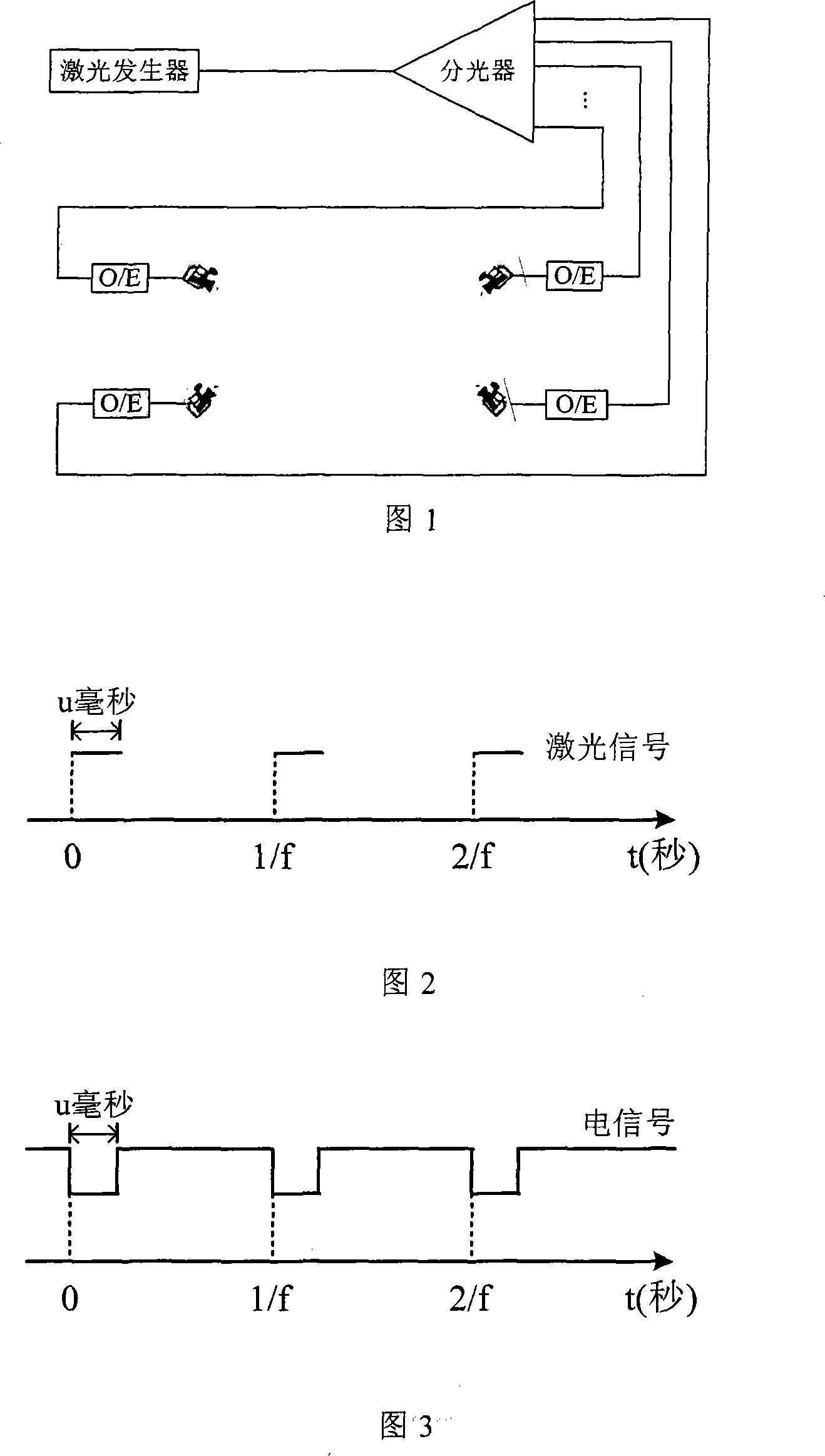
[0017] As shown in FIG. 1 , the embodiment of the present invention includes: a laser generator 1 , an optical fiber 2 , a beam splitter 3 , and a photoelectric converter 4 . The repetitive pulse laser signal generated by the laser generator 1 is transmitted to the optical splitter through the optical fiber 2 as the input pulse laser signal, and the input pulse laser signal is divided into multiple pulse laser signals by the optical splitter 3; each output of the optical splitter 3 The pulsed laser signal is connected to four photoelectric converters 4 through optical fiber 2; the four photoelectric converters 4 perform photoelectric conversion on the input pulsed laser signal, and output pulsed electrical signals; the pulsed electrical signals output by the four photoelectric converters 4 pass th...


PUM


Abstract

A device is provided for synchronizing a plurality of cameras by using a laser splitter, which comprises a laser generator, optical fibers, a light splitter and photoelectric converters. A laser output from the laser generator is transferred to the light splitter via the optical fibers, the light splitter decompose the laser into multi-path lasers; the multi-path lasers output from the light splitter are individually connected to the photoelectric converters via the optical fibers; the photoelectric converters convert the laser signals into electrical pulse signals; the electrical pulse signals, as synchronous signals, externally trigger each cameras for capturing images. The quantities of the optical fiber and the photoelectric converter are determined by the quantity of the cameras. The invention has no distance limitation and solves the problems of prior art, such as interference in remote triggering with electrical pulse signals and serious signal loss.

Description

technical field [0001] The invention relates to a multi-camera synchronization device, in particular to a multi-camera synchronization device using a laser beam splitter. Background technique [0002] When multiple cameras are used to collect multiple images synchronously, the timing of image collection needs to be strictly synchronized to ensure that the user can obtain a complete and continuous frame of images from the specified time, so that objects can be registered and positioned according to the collected images. 3D reconstruction. [0003] At present, camera synchronization methods are divided into external synchronization, internal synchronization (random synchronization), power synchronization, and VD2 pulse synchronization. Generally better cameras will have external synchronization, internal synchronization, power synchronization, and even VD2 pulse synchronization (such as Panasonic and other products). The inner synchronization method has the advantage of simp...

Claims


Application Information

Patent Timeline
Patent Type & Authority Applications(China)
IPC IPC(8): G03B35/08G02B6/42H04N5/225
Inventor 周忠张淑军黄海吴威赵沁平
Owner BEIHANG UNIV
Why Eureka
Try Eureka