Cooler for heater-containing box

A technology of cooling device and storage box, which is applied in the box field of the machine, and can solve problems such as poor welding, time-consuming work, reduction of opening height and air path height, etc.

Active Publication Date: 2008-07-30
PANASONIC CORP
View PDF2 Cites 13 Cited by
  • Summary
  • Abstract
  • Description
  • Claims
  • Application Information

AI Technical Summary

Problems solved by technology

[0026] In addition, when thermally welding the outer peripheral sides of the laminated heat transfer plates, there is a problem that the height of the opening on the outer peripheral side and the height of the air passage may decrease due to thermal shrinkage, and it is required to ensure the height of the opening on the outer peripheral side and the height of the air passage to suppress increase in ventilatory resistance
[0027] In addition, in thermal welding, there is a problem that man-hours are spent on welding work to prevent welding failures, and it is required to reduce man-hours of welding work and improve productivity
[0028] In addition, when the excess thin plate is cut off from the heat transfer plate, burrs (burrs) remain at the inlet or outlet of the air passage, and during heat welding, the opening height of the inlet or outlet may decrease and the airflow resistance may increase due to the burrs. Big problem, it is required to prevent the reduction of the opening height due to the burr and suppress the increase of the ventilation resistance

Method used


Image

  • Cooler for heater-containing box
  • Cooler for heater-containing box
  • Cooler for heater-containing box

Examples


Embodiment approach 1

[0169] Hereinafter, Embodiment 1 of the present invention will be described with reference to FIGS. 1 to 3 .

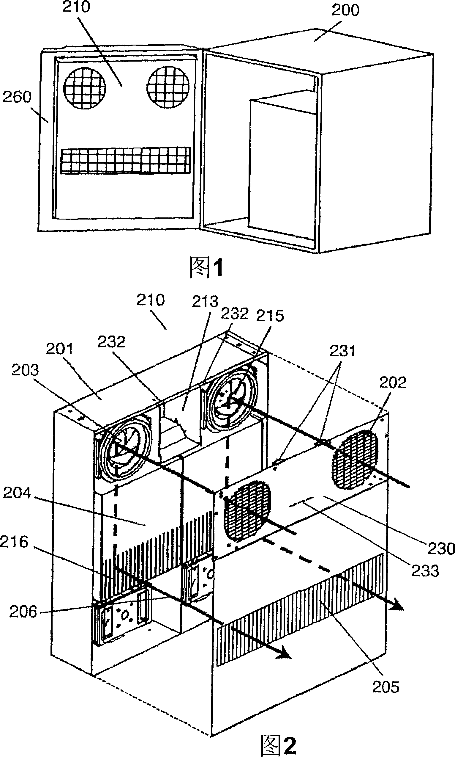
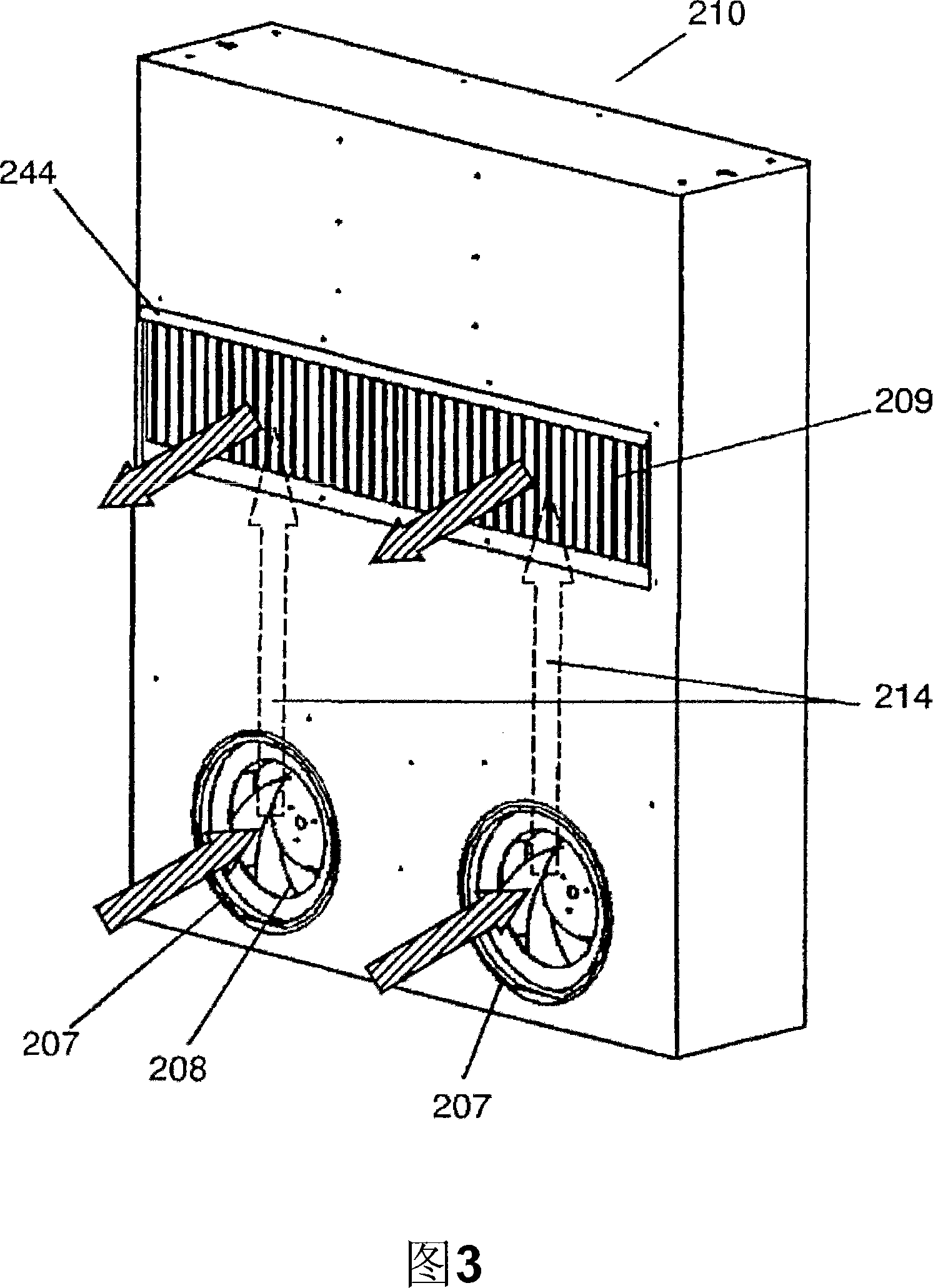
[0170] Fig. 1 is an installation diagram of a heating element storage box cooling device in Embodiment 1 of the present invention, Fig. 2 is an indoor appearance view and a structural diagram of a heating element storage box cooling device in Embodiment 1 of the present invention, and Fig. 3 is The exterior view of the outdoor side of the heating element storage box cooling device in Embodiment 1 of the present invention shows a state in which a plurality of heating element storage box cooling devices 100 are installed in the horizontal direction (each figure shows a case where two are installed).

[0171] The heating element storage box cooling device 210 is installed on the door 260 of the heating element storage box 200, forming a "door-integrated" installation structure.

[0172] In addition, although the heating element storage box cooling device 210 is installed...

Embodiment approach 2

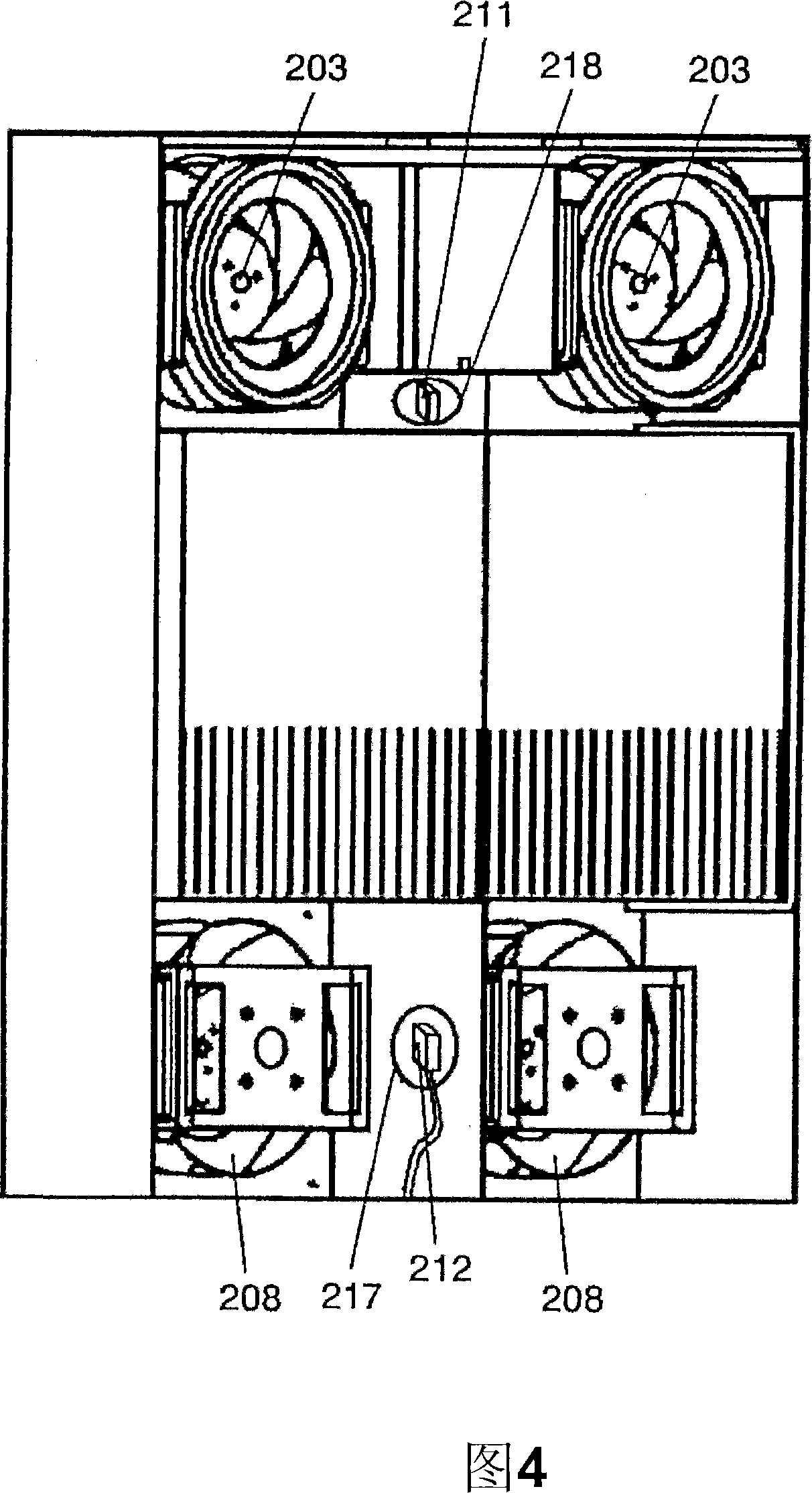
[0187] Next, Embodiment 2 of the present invention will be described with reference to FIG. 4 .

[0188] Fig. 4 is a block diagram showing a temperature detector-related structure of the heating element storage box cooling device according to Embodiment 2 of the present invention, showing a state in which a plurality of heating element storage box cooling devices are installed. In FIG. 4 , the same reference numerals are used for the same constituent elements as those in FIGS. 2 and 3 , and description thereof will be omitted.

[0189] The internal air temperature detector 211 that detects the temperature of the internal air is arranged on the internal air through hole 218 provided between the internal air blowers 203 of the heating element storage box cooling devices A, and the external air temperature of the external air temperature is detected. The detector 212 is disposed on the outside air through-hole 217 provided between the outside air blowers 208 of the heating elemen...

Embodiment approach 3

[0192] Next, Embodiment 3 of the present invention will be described with reference to FIG. 5 .

[0193] Fig. 5 is a structural diagram related to a heat insulator of the heating element storage box cooling device according to Embodiment 3 of the present invention. In FIG. 5 , the same reference numerals are used for the same constituent elements as those in FIG. 2 , and description thereof will be omitted.

[0194] On the heating element storage box cooling device 210, for positioning the heat exchanger 204, for example, a heat insulator 219 made of foamed styrene is provided with a guide rail 220 formed at the edge to be connected to the heat exchanger 204. The lower end abuts against the convex wall.

[0195] According to the above structure, the heat exchanger 204 can be installed and positioned so that the lower end of the heat exchanger 204 abuts on the guide rail 220, so the installation is easy, the arrangement structure is simple, and the production and maintenance a...


PUM


Abstract

There is provided a cooler for heater-containing box in which an outside air fan for carrying air on an outside air path and an inside air fan for carrying air on an inside air path are arranged such that a rotating shaft of each fan is in parallel with an air intake direction, and a heat exchanger for exchanging sensible heat of outside air and inside air is arranged between the outside air path and the inside air path such that a suction port at a longitudinal air-path side of the heat exchanger is aligned with a blowout port of the fan. The cooler for heater-containing box capable of making the depth thinner can be provided.

Description

technical field [0001] The present invention relates to a box structure installed outdoors, which has heating elements such as electronic components inside, which generate a large amount of heat, requires cooling even in winter, and has performance and lifespan that are greatly affected by temperature. Cases for precision machines, especially as regards their cooling devices. Background technique [0002] In recent years, the high performance of electronic components and the high density of electronic components relative to control substrates have increased, and the amount of heat generated from the control substrates has increased dramatically. Along with this, the temperature inside the box tends to rise, and the operation assurance and product life of the electronic components on the control board are greatly affected by the temperature inside the box. Therefore, reliability cannot be ensured unless the temperature in the box is cooled below a certain level. [0003] Fo...

Claims


Application Information

Patent Timeline
Patent Type & Authority Applications(China)
IPC IPC(8): H05K7/20F24F7/08F25D1/00F28F3/08
CPCF28D9/0037H05K7/206Y02B30/563F24F12/006Y02B30/16F28D9/0068F28F3/048F28F2250/108Y02B30/56F24F7/08F28F3/08
Inventor 中野裕二萩本桂辅舟田直之山口俊和松本睦彦最首和树柴田洋
Owner PANASONIC CORP
Why Eureka
Try Eureka