Blast-furnace furnace-arch maintenance robot movement mechanism

A motion mechanism and robot technology, applied in the direction of manipulators, auxiliary devices, claw arms, etc., can solve the problems of workers falling down, life-threatening, low efficiency, etc., to reduce friction and wear, facilitate control, and meet engineering precision requirements Effect

Inactive Publication Date: 2008-08-06
SHANGHAI UNIV
View PDF0 Cites 18 Cited by
  • Summary
  • Abstract
  • Description
  • Claims
  • Application Information

AI Technical Summary

Problems solved by technology

Now this work is done manually. Not only is the efficiency low and the quality is poor, workers are also in danger of falling down, posing a threat to life

Method used


Image

  • Blast-furnace furnace-arch maintenance robot movement mechanism
  • Blast-furnace furnace-arch maintenance robot movement mechanism
  • Blast-furnace furnace-arch maintenance robot movement mechanism

Examples


Embodiment Construction

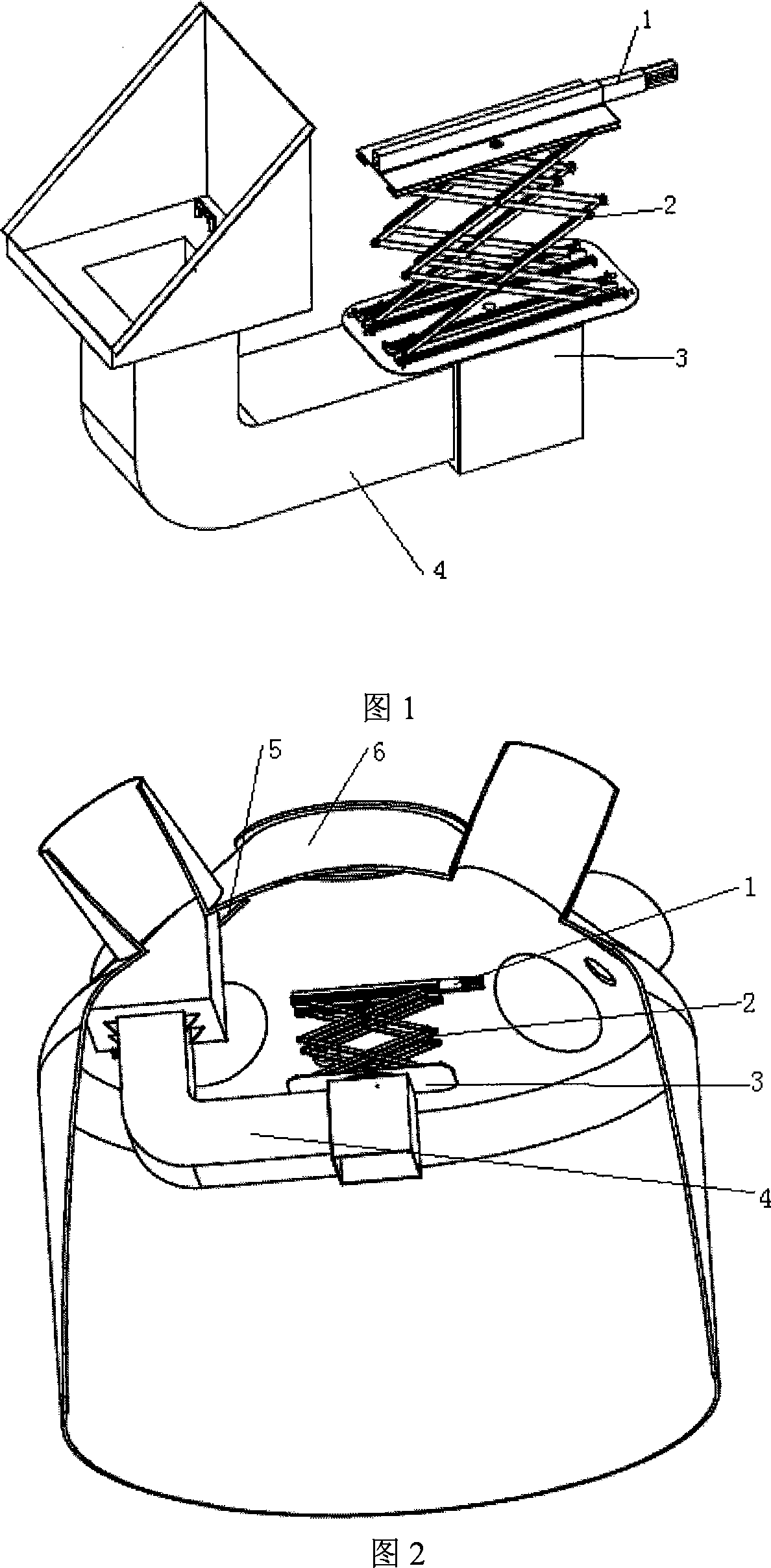
[0026] A preferred embodiment of the present invention is described as follows in conjunction with accompanying drawing: Referring to Fig. 1, Fig. 2, Fig. 3 and Fig. 4, this blast furnace top maintenance robot kinematic mechanism adopts the mechanical kinematic mechanism of cylindrical coordinate type, and it contains three degrees of freedom, In this structure, three sub-mechanisms each realizing one degree of freedom movement are assembled together and fixed on the support frame 4 to form an overall structure. Its specific implementation is completed through the coordinated operation of three sub-organizations, which rotate or move in the cylindrical coordinate space, and finally make the working tool at the end reach the expected surface of the inner wall of the blast furnace roof.

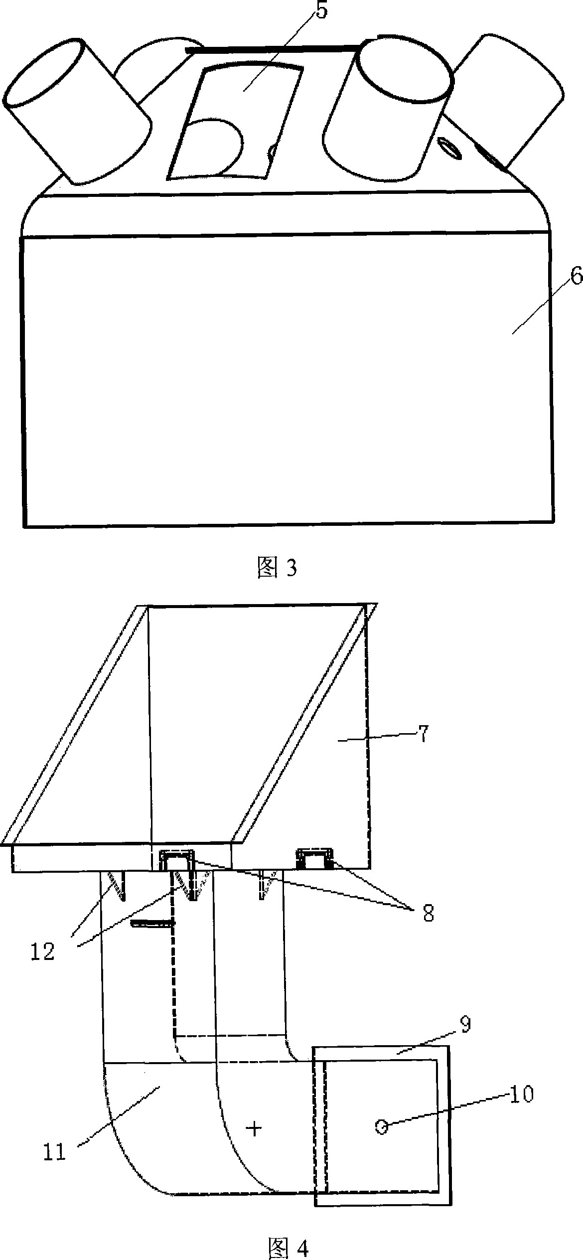
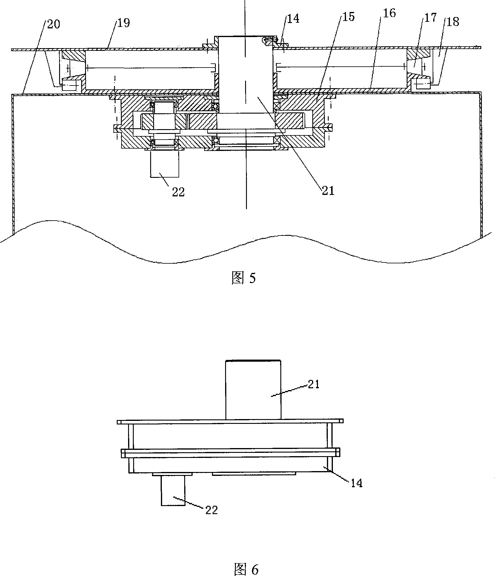
[0027] Referring to Fig. 4 and Fig. 5, the support frame 4 is a large "L"-shaped integral shell 11, the thick end part 9 of the head 7 is thin, and the head 7 is in contact with the manhole 5 on...


PUM


Abstract

The invention relates to a motion mechanism of a blast furnace top maintaining robot, comprising a support frame which is fixedly connected with the blast furnace top manhole and is positioned in the cavity of the blast furnace top. The support frame is provided with a rotary table, of which the rotary center is positioned in the center of the blast furnace top. The rotary table is provided with a lifting platform in which a telescopic boom is arranged. The structure well realizes a three degrees motion of the structure. With simple structure, good rigidity, the motion mechanism of the blast furnace top maintaining robot can automatically and precisely control the moving position and meet the operation requirement of the industry robot.

Description

technical field [0001] The invention relates to a kinematic mechanism of an industrial robot for blast furnace top maintenance, and belongs to the technical field of special large-scale industrial robots. Background technique [0002] In the maintenance process of large-scale equipment in enterprises, some difficulties or dangers are often encountered, such as the maintenance of the blast furnace roof with a volume of 2500 cubic meters and a height of about 40 meters (as shown in Figure 1), and the welding of the inside of the conical top of the blast furnace Embedding steel feet and spraying refractory materials is a very difficult task. Now this work is done manually. Not only is the efficiency low and the quality is poor, workers are also in danger of falling down, which poses a threat to life. So consider using large-scale industrial robots to replace workers. Contents of the invention [0003] The object of the present invention is to solve the problems existing in ...

Claims


Application Information

Patent Timeline
Patent Type & Authority Applications(China)
IPC IPC(8): B25J19/00B25J18/02B23K37/02B05B15/06B05B15/10
Inventor 张国贤金健张利勇冀卫东
Owner SHANGHAI UNIV
Why Eureka
Try Eureka