Foot brake structure for minisize motorcycle

A foot brake, motorcycle technology, applied in bicycle brakes, foot start devices, bicycle accessories, etc., can solve the problems of occupying a large space, increasing weight, and reducing the degree of freedom of design, so as to increase the degree of design freedom and improve the Assemblability, the effect of firm support

Active Publication Date: 2008-08-06
HONDA MOTOR CO LTD
View PDF1 Cites 5 Cited by
  • Summary
  • Abstract
  • Description
  • Claims
  • Application Information

AI Technical Summary

Problems solved by technology

[0007] When the distance between the brake shaft 9 and the foot pedal Ps is large, the distance between the brake shaft 9 and the tread surface f becomes longer. As a result, the foot brake pedal BP becomes large, and the structure supporting the foot brake pedal BP also becomes large. , resulting in increased weight and occupying a larger space
In addition, when the shaft guide 8 is attached to the large-diameter, thick-walled main pipe 3, processing is very difficult, so the degree of freedom in design is reduced, and processing man-hours and costs are increased.

Method used


Image

  • Foot brake structure for minisize motorcycle
  • Foot brake structure for minisize motorcycle
  • Foot brake structure for minisize motorcycle

Examples


Embodiment Construction

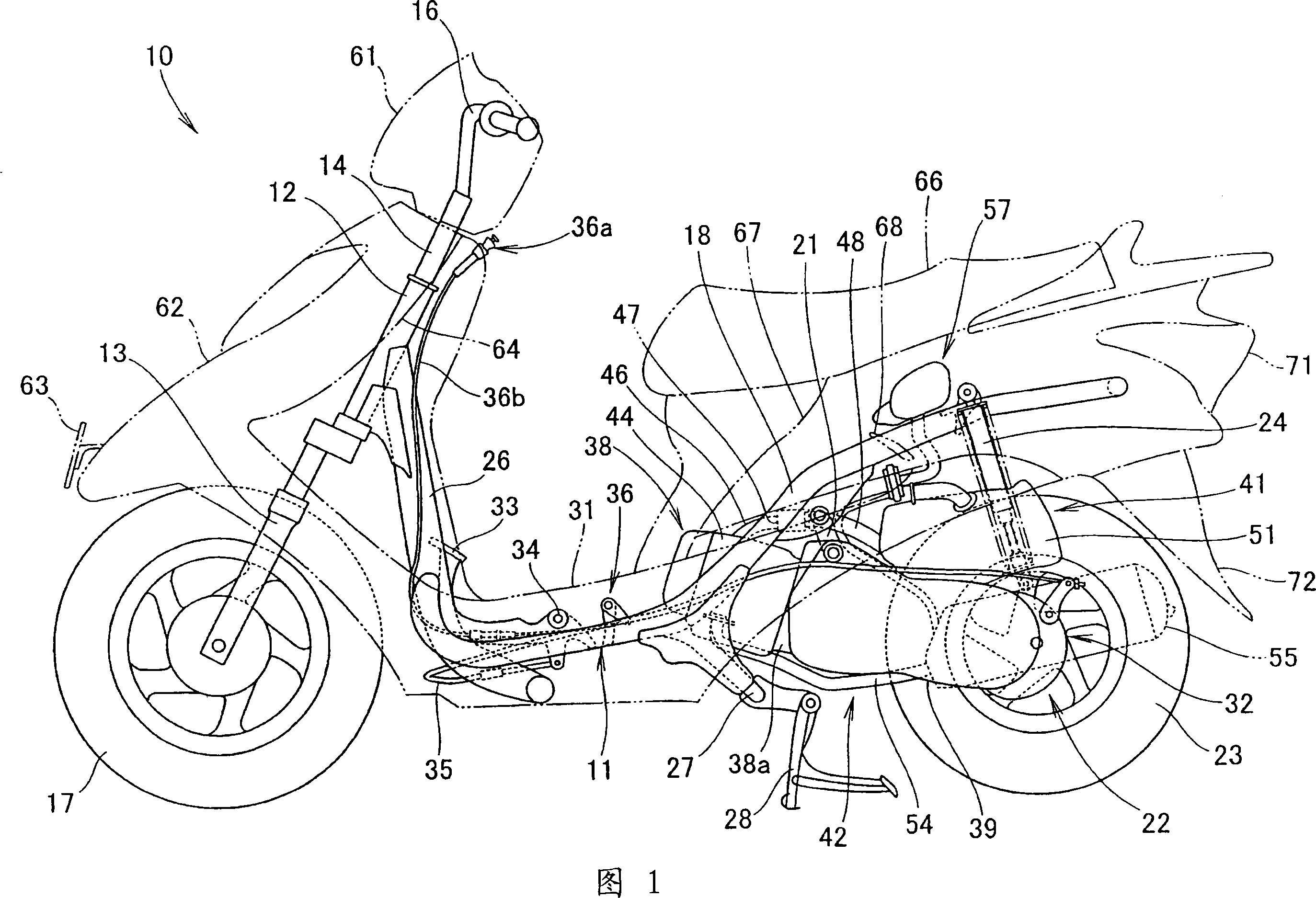
[0058] Preferred embodiments for carrying out the present invention will be described based on the drawings. In addition, the drawing is a figure seen from the direction shown by a symbol.

[0059]FIG. 1 is a side view of a small motorcycle vehicle adopting the foot brake structure of the present invention. A two-wheeled motor vehicle 10 is a two-wheeled motor vehicle having the following structure. , the operating handle 16 is installed on the steering shaft 14 provided on the front fork 13, the front wheel 17 is installed on the lower end of the front fork 13, and the power unit 22 is supported on the main frame constituting the vehicle frame 11 through the connecting rod 21 to swing up and down freely. 18, the rear wheel 23 is installed on the rear end of the power unit 22, and the rear shock absorber unit 24 is installed across the rear end of the power unit 22 and the rear portion of the main frame 18.

[0060] The body frame 11 is composed of a front pipe 12, a lower fr...


PUM


Abstract

The invention provides a foot brake structure of a small motorcycle vehicle, which can realize the miniaturization of the foot brake structure, increase the degree of freedom in design, and reduce processing hours and costs. In the foot brake structure of this small motorcycle vehicle, a pair of left and right pedals (31) supported by the main frame (18) are arranged between the handlebar and the front and rear double seats, and the brakes for the rear wheels that brake the rear wheels are operated. The brake pedal (33) of the device can be rotatably installed on the main frame (18), and the pedal part (33b) of the brake pedal (33) protrudes from the pedal (31) and is configured. The pedal (31) constitutes the vehicle frame The support plate (81) of a part of (11) is supported, and the fulcrum (34) of pedal (33) is provided with on the support plate (81), and this fulcrum (34) is configured on the main frame 18 from the side. above and below the pedal (31).

Description

technical field [0001] The invention relates to an improvement in the structure of a foot brake of a small motorcycle vehicle. Background technique [0002] As a conventional foot brake structure for a scooter, there is known a structure in which a rear wheel brake is operated by operating a foot brake pedal protruding above the pedal (for example, refer to Patent Document 1). [0003] Patent Document 1: (Japanese) Patent No. 3447470 [0004] FIG. 1 , FIG. 3 , and FIG. 4 of Patent Document 1 will be described below. [0005] The main pipe 3 is disposed below the footboard Ps of the scooter so as to extend in the front-rear direction of the vehicle, and a cylindrical shaft guide 8 is attached to the main pipe 3 through the main pipe 3 in the vehicle width direction. The brake shaft 9 Rotatably inserted into the shaft guide 8, a foot brake pedal BP is installed at one end of the brake shaft 9, and a relay rod 11 is installed at the other end of the brake shaft 9, and the rel...

Claims


Application Information

Patent Timeline
Patent Type & Authority Applications(China)
IPC IPC(8): B62L3/04B60T7/06
Inventor 中野润一户泽英昭
Owner HONDA MOTOR CO LTD
Why Eureka
Try Eureka