Oxygen sensor heater control methods and systems

An oxygen sensor and control system technology, applied in electrical control, engine control, fuel injection control, etc., can solve problems such as oxygen sensor rupture

Inactive Publication Date: 2008-08-06
GM GLOBAL TECH OPERATIONS LLC
View PDF1 Cites 11 Cited by
  • Summary
  • Abstract
  • Description
  • Claims
  • Application Information

AI Technical Summary

Problems solved by technology

[0005] Rupture of the oxygen sensor may occur due to extreme temperature increases

Method used


Image

  • Oxygen sensor heater control methods and systems
  • Oxygen sensor heater control methods and systems
  • Oxygen sensor heater control methods and systems

Examples


Embodiment Construction

[0016] The following descriptions of preferred embodiments are merely illustrative in nature and in no way limit the invention and its application or use. For simplicity, the same reference numbers are used in the drawings to refer to similar elements. As used herein, the term module refers to an Application Specific Integrated Circuit (ASIC), an electronic circuit, a processor (shared, dedicated or group) and memory, a combinational logic circuit that executes one or more software or hardware programs Or other suitable components that provide the described functionality.

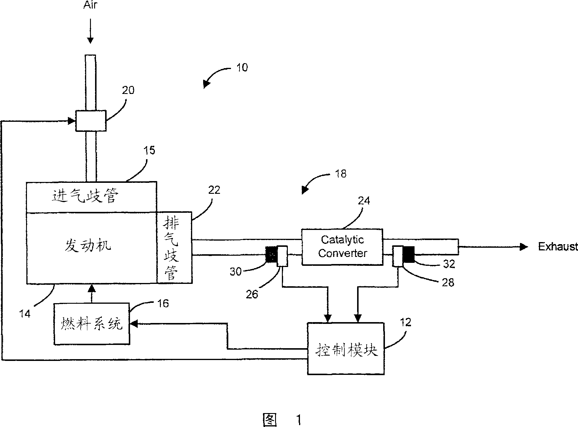
[0017] Referring now to FIG. 1 , a vehicle 10 includes a control module 12 , an engine 14 , a fuel system 16 and an exhaust system 18 . Throttle 20 communicates with control module 12 to control air flow into intake manifold 15 of engine 14 . The amount of torque produced by the engine 14 is proportional to the amount of air (MAF) flowing into the engine 14 . When the A / F ratio is above the stoichiometri...


PUM


Abstract

A control system for an oxygen sensor heater is provided. The control system includes a passive heater control module that generates a heater control signal and measures resistance of the oxygen sensor heater during a first duty cycle. An exhaust temperature mapping module maps the impedance to exhaust temperature. An active heater control module generates a heater control signal based on the exhaust gas temperature during the second duty cycle.

Description

technical field [0001] The present invention relates to methods and systems for controlling an oxygen sensor heater. Background technique [0002] The contents in this section merely provide background technology related to the present disclosure and may not constitute prior art. [0003] The engine control system controls the air and fuel supplied to the engine based on an open-loop or closed-loop feedback method. Open-loop control methods are typically initiated under specific operating conditions such as start-up, cold engine running, heavy load conditions, wide open throttle, and intervening diagnostic events. Engine control systems typically use closed-loop control methods to maintain the air / fuel mixture at or near an understood stoichiometric air / fuel ratio. Closed loop fuel control dictates the required fuel delivery based on the oxygen content in the exhaust. The oxygen content in the exhaust gas is determined by an oxygen sensor located downstream of the engine....

Claims


Application Information

Patent Timeline
Patent Type & Authority Applications(China)
IPC IPC(8): F02D41/14G01N27/406
CPCF02D41/1494F02D41/1446F02D2041/2027
Inventor J·F·亚当斯L·A·阿瓦洛恩D·W·麦金J·A·塞尔J·W·谢基宁J·R·韦尔德约
Owner GM GLOBAL TECH OPERATIONS LLC
Why Eureka
Try Eureka